Main Properties
This area contain all stream-level configuration properties, except those related to protocol header and modifier definitions.
Identification
The Identification properties are used to identify the stream. The Stream ID is a unique stream ID. The Test Payload ID is the test payload ID (TID) carried in the Xena test payload area. This field can be empty if no TID value is needed. The Description is a user-modifiable description label for the stream. The State is the stream enable state.
Property |
Explanation |
|---|---|
Port |
The parent port name |
Stream ID |
The unique stream ID |
Test Payload ID |
The test payload ID (TID) carried in the Xena test payload area. This field can be empty if no TID value is needed. |
Description |
A user-modifiable description label for the stream |
State |
The stream enable state. |
Transmission Profile
Property |
Explanation |
|---|---|
Rate Fraction |
The stream traffic rate expressed as a percentage of the effective rate for the port. |
Packet Rate |
The stream traffic rate expressed as packets per second. |
Bit Rate L2 |
The stream traffic rate expressed as bits per second seen on Layer 2. |
Bit Rate L1 |
The stream traffic rate expressed as bits per second seen on Layer 1. |
Rate Cap |
This command can be used to cap the rate for disabled streams. The button will only be enabled if the sum of the defined stream bandwidth actually exceeds the available port bandwidth. |
Inter Packet Gap |
The calculated mean inter-packet gap with the current TX profile settings. This denotes the space between the end of the preceding packet and the start of the following packet. |
Seq.Packets |
The number of sequential packets sent before switching to the next stream (packets). This property is only configurable when the Port TX Mode is set to Sequential. |
Stop After |
Stop stream transmission after the specified number of packets are sent. This value can be empty or zero, which means that the stream will continue to transmit until traffic is stopped at the port level. The Stop after function is not an option when Port TX Mode is set to Sequential. |
Burst Size |
The number of packets in each burst (packets). Valid range 0-500; in TX mode Burst **: 0-10000. |
Burst Density |
The density of the burst expressed as a percentage value between 0 and 100. A value of 100 means that the packets are packed tightly together, only spaced by the minimum inter-frame gap. A value of 0 means even, non-bursty, spacing. The exact spacing achieved depends on the other enabled streams of the port. Not used when TX port mode is Burst ** |
Inter Packet Gap ** |
Gap between packets in a burst. Only used when TX port mode is Burst |
Inter Burst Gap ** |
Gap between this burst and burst in next stream. Only used when TX port mode is Burst |
Inter Burst Gap |
The calculated inter-burst gap with the current burst settings. This denotes the space between the end of the last packet in the preceding burst and the start of the first packet in the following burst. |
Burst Signature |
A graphical depiction of the current burst settings |
Error Handling
The Error Handling properties are used to control the error handling for the stream.
Property |
Explanation |
|---|---|
Insert Frame Checksum (FCS) |
Control if a valid frame checksum is added to the stream packets. Default is enabled. |
Error Injection |
Specifies the type of error that is injected into the traffic stream. The following types of errors can be specified:
It is only possible to inject errors on a stream if traffic is active on the parent port. |
Inject Error |
Inject a single error of the specified type into the traffic stream. This option is only enabled when traffic is active on the parent port. |
Packet Content
The Packet Content properties are used to control the packet content for the stream.
Property |
Explanation |
|---|---|
Packet Size Type |
The size distribution of the packets transmitted for the stream Important Read how to generate mixed packet size in MIX Weights. |
Packet Auto Size |
If selected XenaManager minimum packet size is auto adjusted so it equals the configured packet size in the stream. |
Minimum Size |
The lower limit of the packet size (if required by the size type) |
Maximum Size |
The upper limit of the packet size (if required by the size type) |
Payload Type |
The type of payload data used in the Xena payload section.
Important When using Incrementing 16-bit or Decrementing 16-bit, you need to check the option Payload Start From 0 to have the payload 00 00 00 01 00 02 00 03 00 04 00 05 … or FF FF FF FE FF FD FF FC FF FB FF FA…. |
Payload Pattern |
The pattern of bytes to be repeated when the type is set to Pattern. |
Payload Pattern Size |
When choosing Pattern as Payload Type, it is possible to define the size of the repeated payload pattern part. |
Ext. Payload Size |
The size of the extended payload if this option has been enabled on the parent port. Refer to Freely Programmable Test Packets (Custom Data Fields) for details. |
Connectivity Check
Property |
Explanation |
|---|---|
IPv4 Gateway Address |
The IPv4 gateway address used to resolve the DMAC address for the stream. Only valid if the stream contains an IPv4 protocol segment. |
IPv6 Gateway Address |
The IPv6 gateway address used to resolve the DMAC address for the stream. Only valid if the stream contains an IPv6 protocol segment. |
Resolve Peer Address |
Send an ARP or NDP request to the peer in order to resolve the MAC address. Only valid of an IPv4 or IPv6 segment has been defined with a valid Dest. IP address is defined. |
Check IP Peer |
Send a PING request to the peer in order to check the connectivity. Only valid of an IPv4 or IPv6 segment has been defined with a valid Dest. IP address is defined. |
The Xena tester will set the Target IP Address in any ARP/NDP request sent from a Xena test port to a value in the following prioritized order:
Stream gateway IP address for the IP version used by the stream if defined.
Port gateway IP address for the IP version used by the stream if defined and stream Dest IP Address is not in same subnet as the port gateway (the legacy method).
Stream Dest. IP Address
Important
You can create multiple IPv4/IPv6 streams on a port to simulate traffic from multiple IPv4/IPv6 client endpoints behind a physical port. Each endpoint can have different source MAC addresses and source IP addresses. At this point, the MAC address of the physical test port become unimportant for testing because it is the “virtual clients” behind that matter. However, to make each “virtual client” successfully resolve the destination’s MAC address (either the gateway or the destinations), you must configure (or auto-generate) the port’s ARP/NDP Address Tables accordingly by clicking the Generate in Main Port Config
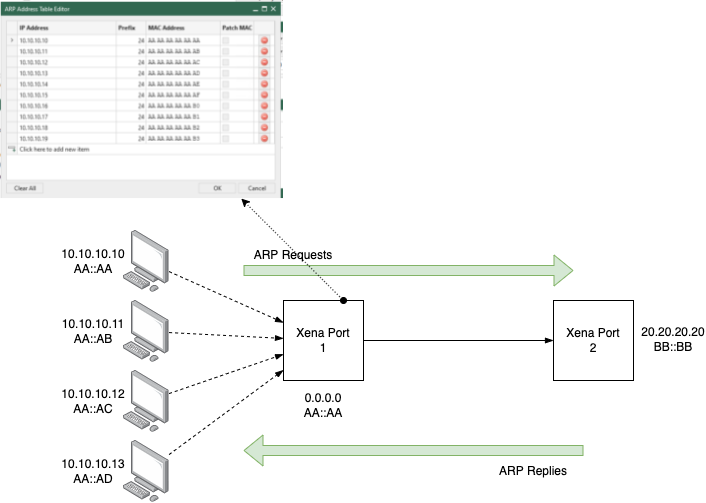
Fig. 5.104 Generate ARP/NDP table for the port in order to successfully do ARP/NDP resolution for streams