Main Port Config
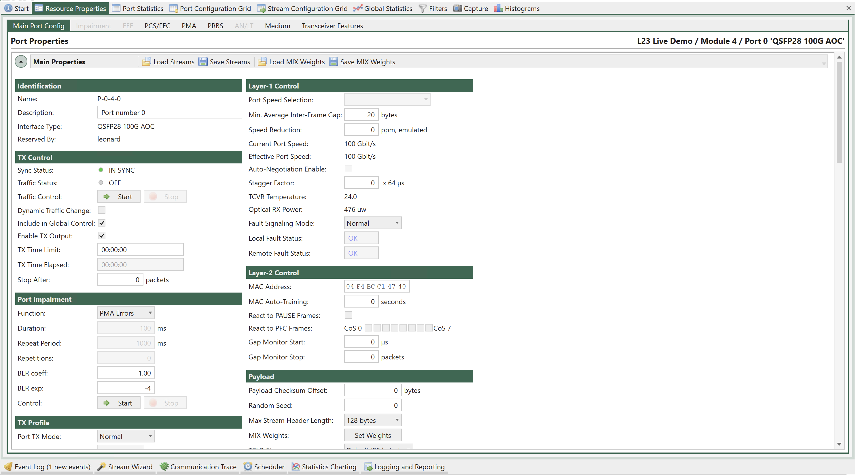
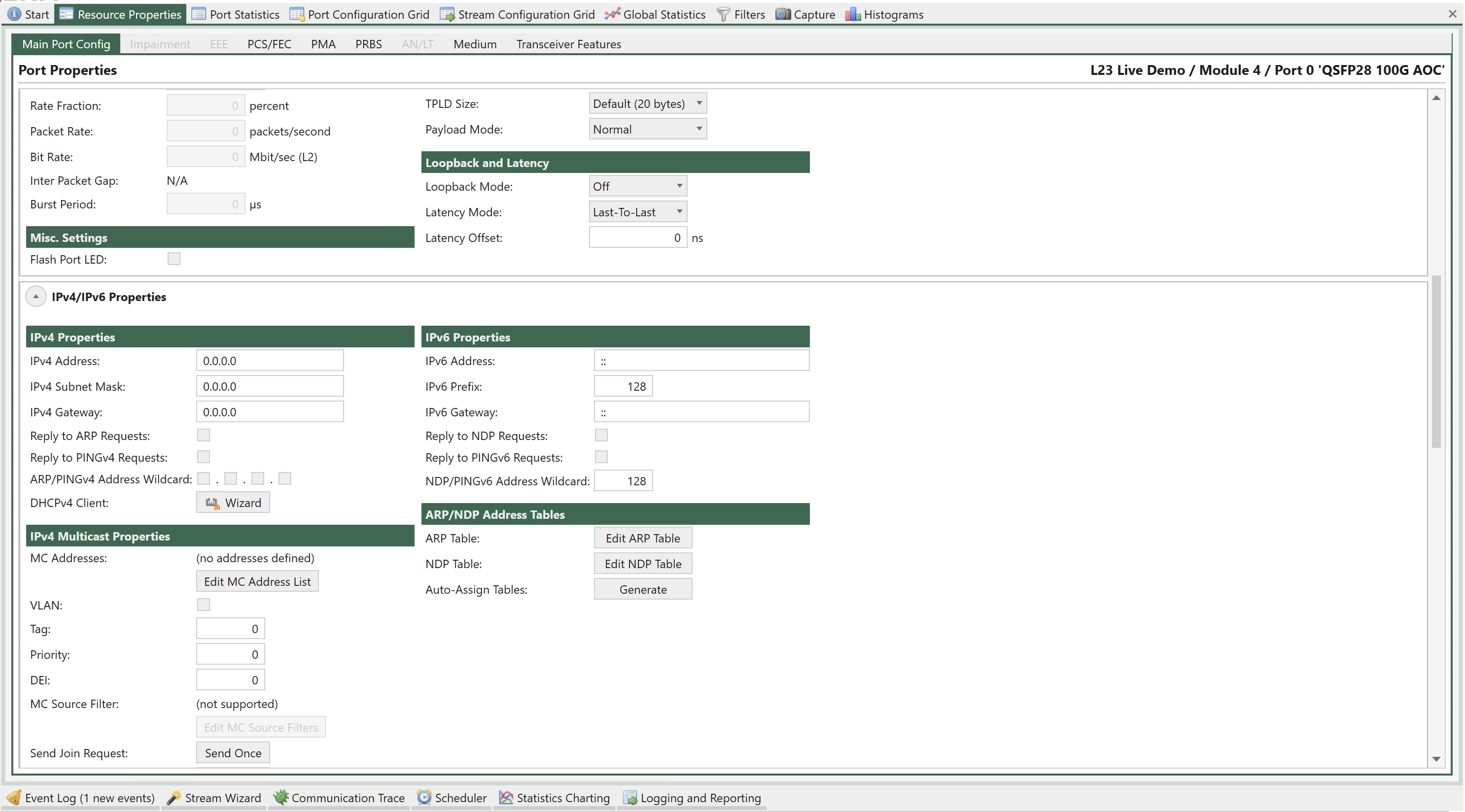
Fig. 5.6 Port Properties - Main
Identification
Property |
Explanation |
|---|---|
Name |
The unique short-form name for the port |
Description |
A user-definable string label for the port |
Interface Type |
The Xena port interface type |
Reserved By |
If the port has been reserved by a user, this field will show the username of the reserver. |
TX Control
Property |
Explanation |
|---|---|
Sync Status |
The current sync state for the port. The port can either be |
Traffic Status |
The current traffic status for the port. |
Traffic Control |
This button enables you to either start or stop traffic on the port. Or restart traffic with dynamic changes seamlessly. |
Dynamic Traffic Change |
If this option is checked, the port will allow dynamic changes to the traffic while the traffic is running on the port. As soon as the Restart button is pressed, traffic is changed dynamically seamlessly. |
Include in Global Control |
If this option is checked and the port is part of the current testbed the port traffic state will be controlled by the Start/Stop buttons in the Global Statistics panel. |
Enable TX Output |
Determines if the port should enable its transmitter, or keep the outgoing link down |
TX Time Limit |
The maximum amount of time the port should transmit when enabled. If set to zero the port will transmit until stopped manually. |
TX Time Elapsed |
The amount of time the port has currently been transmitting |
Stop After |
Stop port transmission after the specified number of packets are sent |
Note
(*) Feature is only supported by legacy 40G/100G ports. (**) Feature requires software release 76 or higher.
TX Profile
Property |
Explanation |
|---|---|
Port TX Mode |
This property determines the scheduling mode for outgoing traffic from the port, i.e. how multiple streams are merged onto one physical port. |
Rate Fraction |
The port-level rate of the traffic transmitted for a port in sequential TX mode, expressed as a percentage of the effective rate for the port. Only available when the Port TX Mode is set to Sequential. |
Packet Rate |
The port-level rate of the traffic transmitted for a port in sequential TX mode, expressed in packet per second. Only available when the Port TX Mode is set to Sequential. |
Bit Rate |
The port-level rate of the traffic transmitted for a port in sequential TX mode, expressed in bits per second. Only available when the Port TX Mode is set to Sequential. |
Inter Packet Gap |
The calculated mean inter-packet gap with the current TX profile settings. Only available when the Port TX Mode is set to Sequential. |
Burst Period |
Time in micro seconds from start of sending a group of bursts till start of sending next group of bursts. Only available when the Port TX Mode is set to Burst. |
Important
The scheduling mode for outgoing traffic from the port, specifying how multiple logical streams are merged onto one physical port. There are four primary modes:
Normal Interleaved: The streams are treated independently, and are merged into a combined traffic pattern for the port, which honors each stream’s ideal packet placements as well as possible. This is the default mode.
Strict Uniform: This is a slight variation of normal interleaved scheduling, which emphasizes strict uniformity of the inter-packet-gaps as more important than hitting the stream rates absolutely precisely.
Sequential: Each stream in turn contribute one or more packets, before continuing to the next stream, in a cyclical pattern. The count of packets for each stream is obtained from the Stop After of the stream. The individual rates for each stream are ignored, and instead the overall rate is determined at the port-level. This in turn determines the rates for each stream, taking into account their packet lengths and counts. The maximum number of packets in a cycle (i.e. the sum of Stop After for all enabled streams) is 500. If the packet number is larger than 500, will be returned when attempting to start the traffic.
Burst: When this mode is selected, frames from the streams on a port are sent as bursts as depicted below: The Burst Period is defined in the Burst Period. For the individual streams, the number of packets in a burst is defined by the Burst Size in the stream transmission profile. Refer to the Fig. 5.7 below for an illustration of the burst mode.
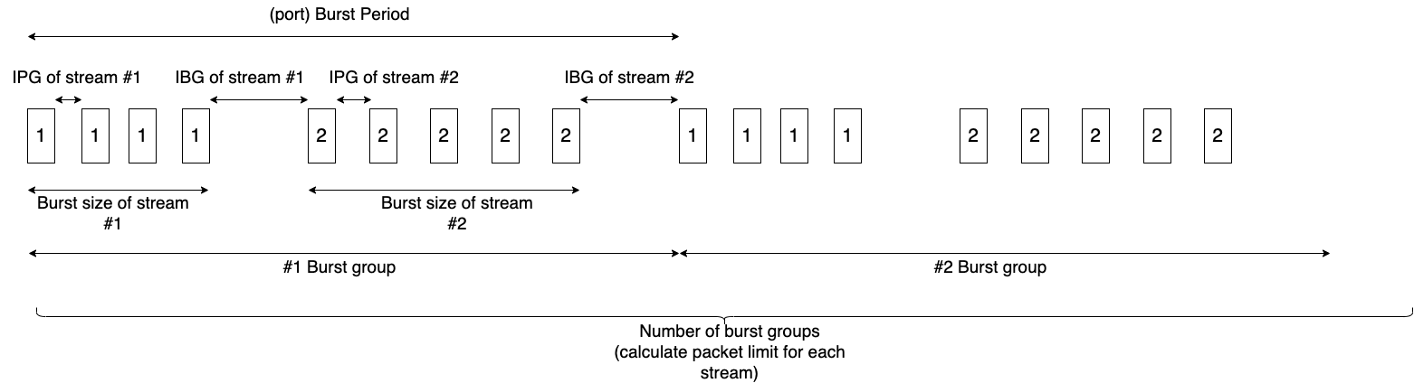
Fig. 5.7 Port TX Burst Mode
Port Impairments
This section describes impairments which will affect the entire port. I.e it will affect all streams defined for the selected port.
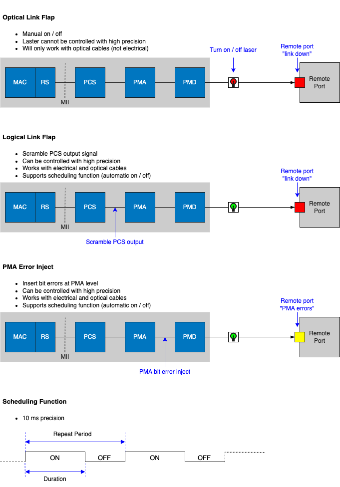
Fig. 5.8 Port impairments
Link Flap
TG port can be configured to emulate that the physical link is down or unstable. This feature is called Link Flap. Link flap is implemented in 2 ways: Logical Link Flap and Optical Link Flap.
Notice that link flap is configured at a port level and will affect all flows configured for the selected port.
Note
Note that logical link flap and PMA error pulse inject (see Section PMA Error Injection) are mutually exclusive.
Logical Link Flap
Link Flap under Port Impairments is Logical Link Flap. Logical link flap is implemented by scrambling the Tx PCS encoding to prevent the peer port from getting a link. It is not implemented by turning the physical transmitter on or off.
Logical Link Flap works for both electrical cables (DAC cables) and optical cables.
Logical link flap is configured under the Main Port Config tab as illustrated in Fig. 5.9.
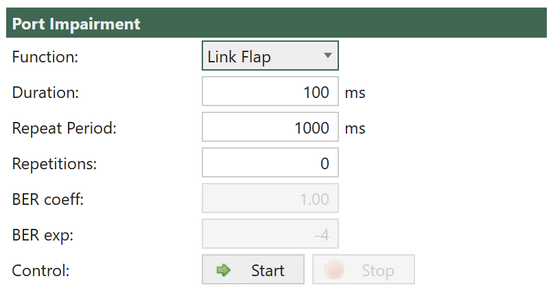
Fig. 5.9 Configuration of Logical Link Flap.
Logical Link Flap supports a repetitious pattern, where the link is taken down for a period (Duration) and then brought up again. This is repeated after a configurable time (Repeat Period). The flapping is repeated a configurable number of times or continuously (Repetitions).
Please observe that Link Flap is configured at a port level and will affect all streams configured for the selected port.
Pressing Start will start the configured link flap, pressing Stop will stop any ongoing link flapping.
Logical link flap is configured as follows:
Parameter |
Description |
|---|---|
Duration |
Duration of the link flap. |
Repeat Period |
Period after which to restart link flap. |
Repetitions |
How many times to restart the link flap. |
Optical Link Flap
To simulate the event of the optical link going down, it is possible to manually turn the optical transmitter off and on.
Optical link flap only works for optical cables, i.e., it will not work with DAC cables for instance. Optical link flap does not support repetitious patterns as described above for logical link flap.
Optical link flap is configured on the Main Port Config tab as illustrated in Fig. 5.10.
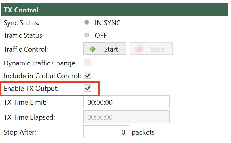
Fig. 5.10 Configuration of Optical Link Flap.
Use Enable Tx Output to turn the optical transmitter off / on.
PMA Error Injection
PMA Error Injection allows the user to insert bit errors onto the link.
Please observe that PMA Error Injection is configured at a port level and will affect all streams configured for the selected port.
Property |
Explanation |
|---|---|
Function |
Enables Link Flap or PMA error injection. |
Duration Link Flap |
Time in ms the link is taken down. Range: 10 ms to 1000 ms; step size 1 ms. |
Repeat Period |
Time between link down. Range:10 ms to 50000 ms; step size 10 ms. “Repeat Period” must be larger than “Duration”. |
Repetitions Link Flap |
Number of Link Flaps. Range: 0, 1 to 64K; step size 1. 0 = continuous until stopped. |
BER Coeff |
PMA Error injection: Bit Error Rate coefficient. Range 0.01 to 9.99; step size 0.01. |
BER Exp |
PMA Error injection: Bit Error Rate exponent. Range -17 to -3; step size 1 |
Control |
Pressing Start will start the configured Link Flap/PMA Error injection, pressing Stop will stop any ongoing Link Flap/PMA Error injection. |
Misc. Settings
Property |
Explanation |
|---|---|
Flash Port LEDs |
If checked, this property will make the test port LED for a particular port flash on and off with a 1-second interval. This is helpful when you need to identify a specific port within a chassis. |
Layer-1 Control
Property |
Explanation |
|---|---|
Port Speed Selection |
Controls the port speed selection. This property is only available for ports that support a configurable port speed. |
Min. Average Inter-Frame Gap |
The minimum average total interframe gap (including preamble and SFD) |
Speed Reduction |
Allows you to specify a speed reduction value for the port. The speed reduction is specified as a PPM value between 0 and 100 in steps of 10. The speed reduction is applied to the transmit side of a port, resulting in an effective traffic rate that is slightly lower than the rate of the physical interface. Speed reduction is effectuated by inserting short idle periods in the generated traffic pattern to consume part of the port’s physical bandwidth. The port’s clock speed is not altered. |
Current Port Speed |
The currently detected port speed |
Effective Port Speed |
The effective speed of the port taking any configured speed reduction into account. |
Auto-Negotiation Enable |
Controls whether the port will support auto-negotiation |
BroadR-Reach Mode |
Controls whether a BroadR-Reach transceiver will be in Note We support Technica Engineering BroadR-Reach transceivers.
|
Stagger Factor |
This property delays the start of traffic generation on one port relative to the activation of global start. The delay is programmed in steps of 64 µs. The Stagger Factor will work between ports on test modules installed in the same chassis. NB: This requires that Sync.Start in Global Stats. under the Options tap has been checked. |
TCVR Temperature |
The currently detected transceiver temperature if supported by the transceiver. |
Optical RX Power |
The currently detected received optional power. This property value is only available for optical ports if supported by the transceiver. |
Fault Signaling Mode |
Sets the remote/local fault signaling behavior of the port (performed by the Reconciliation Sub-layer). The following modes can be configured:
|
Local Fault Status |
Indicates Reconciliation Sub-layer signaling status for local port. Status is either OK or Fault |
Remote Fault Status |
Indicates Reconciliation Sub-layer signaling status for remote port. Status is either OK or Fault |
Layer-2 Control
Property |
Explanation |
|---|---|
MAC Address |
The port MAC address |
MAC Auto-Training |
The interval in seconds with which the port should broadcast a MAC learning frame. Set to 0 to disable. |
React to PAUSE Frames |
Control whether the port should react to received PAUSE frames |
React to PFC Frames |
Control whether the port should react to received PFC (Priority Flow Control) frames. Use check boxes to select which priority levels the port reacts to. |
Gap Monitor Start |
Specifies the time period that will trigger the gap monitor start. The maximum allowed gap between packets, in microseconds, 0 to 134.000 microseconds. (0 = disable gap monitor) |
Gap Monitor Stop |
Specifies the number of packets to receive to stop the gap monitor. The minimum number of good packets required, 0 to 1024 packets. (0 = disable gap monitor) |
Note
The gap-start and gap-stop criteria for the port’s gap monitor. The gap monitor expects a steady stream of incoming packets, and detects larger-than-allowed gaps between them. Once a gap event is encountered it requires a certain number of consecutive packets below the threshold to end the event.
Refer to XOA CLI Documentation for more details.
Payload
Property |
Explanation |
|---|---|
Payload Checksum Offset |
The offset where payload checksum calculation starts. Valid values: 0; 8-127. |
Random Seed |
Used when generating traffic that requires random variation in packet length, payload, or modified fields |
Max Stream Header Length |
The maximum length of the defined stream headers. If you increase this you will at the same time reduce number of streams supported by the port. For a port that by default supports 256 streams |
MIX Weights |
Specify the weights for the MIX size packet distribution if supported by the port. See also Read details in MIX Weights. |
TPLD Size |
Specify the size of the TPLD for the port streams if supported by the port.
When the TPLD Size is changed, it will affect ALL streams on the port. See also Read more at Test Payload. |
Payload Mode |
Specify the payload mode used for the port streams if supported by the port. The following options are available:
|
MIX Weights
Internet Mix or IMIX refers to typical internet traffic traversing network equipment such as routers, switches or firewalls. When measuring equipment performance using an IMIX of packets, the performance is assumed to resemble what can be seen in “real-world” conditions.
IMIX configuration is per port. It means each test port can be configured a certain IMIX pattern.
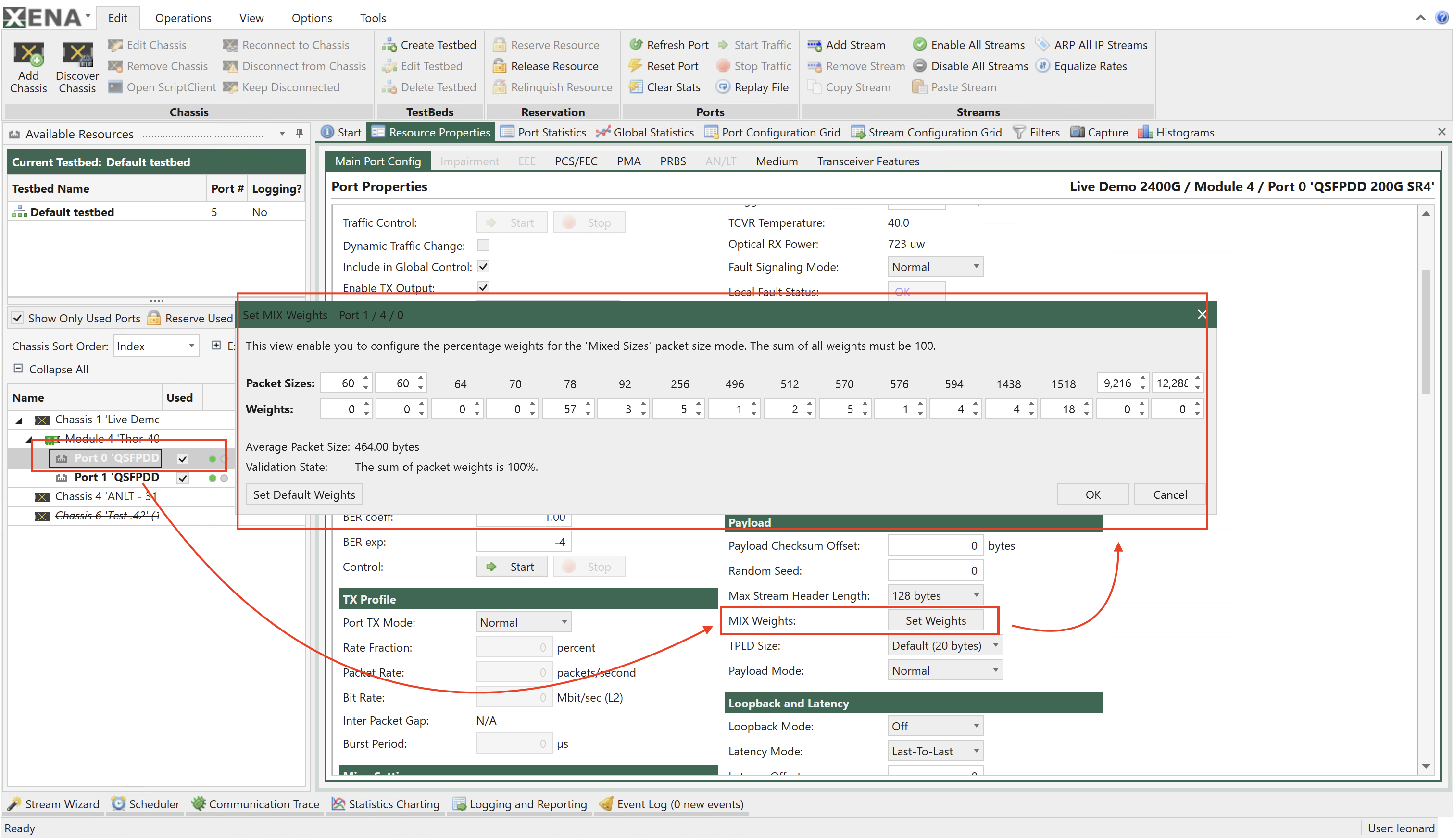
Fig. 5.11 Port MIX weights configuration
Each port has the same default IMIX configuration. If you want to customize the configuration, you should follow the steps:
Reserve a test port.
Click the port and find , click Set Weights.
Configure the desired IMIX.
You can save the port’s IMIX weight configuration by clicking Save MIX Weights on the top bar.
You can also load a IMIX weight configuration to the port by clicking Load MIX Weights.
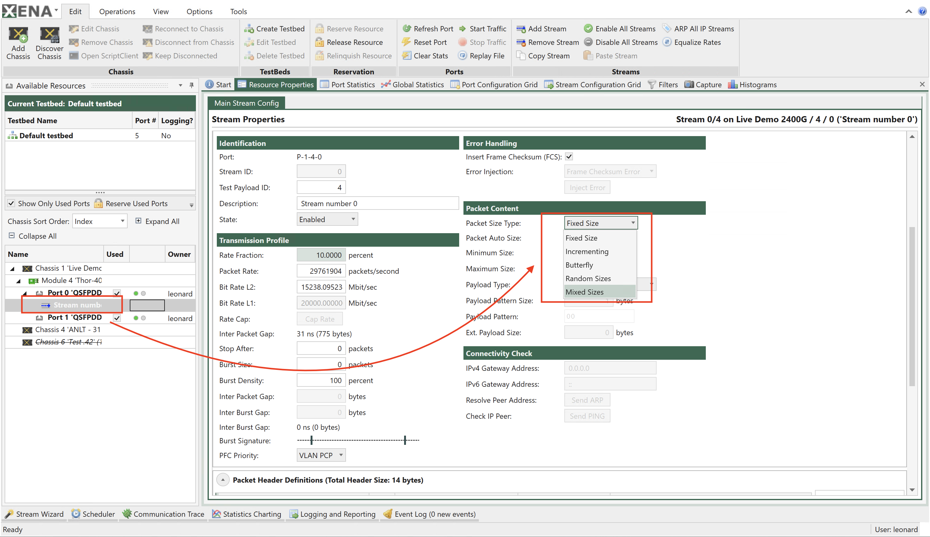
Fig. 5.12 Stream MIX weights selection
To use the configured IMIX to generate packets, you should follow the step:
Create a stream on the port you have configured IMIX weights.
Click the stream and find , and select Mixed Sizes.
The stream will generate packet sizes based on the port’s IMIX weight configuration.
Loopback and Latency
Property |
Explanation |
|---|---|
Loopback Mode |
The port loopback mode. (illustrated in Fig. 5.13)
Refer to P_LOOPBACK in XOA CLI Documentation for more details. |
Latency Mode |
The port latency calculation mode. Latency is measured by inserting a time-stamp in each packet when it is transmitted, and relating it to the time when the packet is received. There are four separate modes for calculating the latency:
Refer to P_LATENCYMODE in XOA CLI Documentation for more details. |
Latency Offset |
The calibrated latency offset value. |
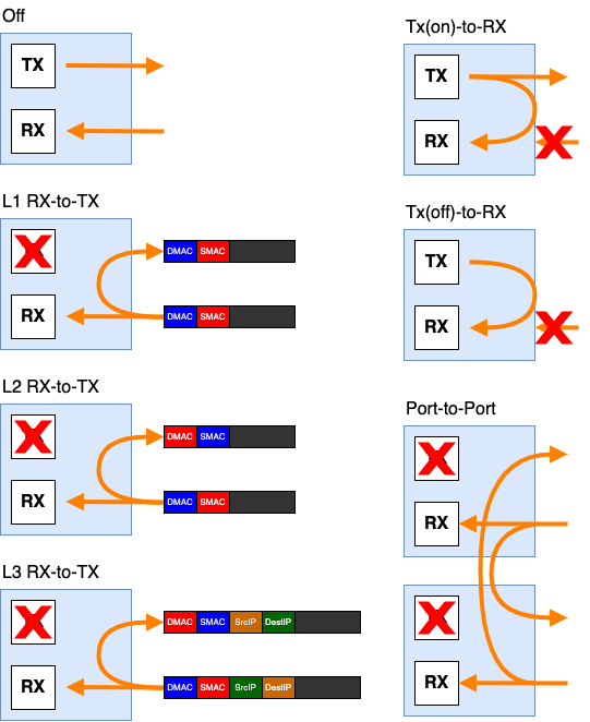
Fig. 5.13 Loopback Mode
Important
As shown in the figure above, the port won’t provide TX counters, when the port loopback mode is set to the following values:
L1 RX-to-TX
L2 RX-to-TX
L3 RX-to-TX
Port-to-Port
IPv4 Properties
Property |
Explanation |
|---|---|
IPv4 Address |
The IPv4 network address for the port. The address is used as the default source address field in the IP header of generated stream traffic, and the address is also used for support of the ARP and PING protocols. |
IPv4 Subnet Mask |
The IPv4 subnetwork mask for the port. |
IPv4 Gateway |
The default IPv4 gateway address for the port. |
Reply to ARP Requests |
Control whether the port will reply to incoming ARP requests |
Reply to PINGv4 Requests |
Control whether the port will reply to incoming PING requests |
ARP/PINGv4 Address Wildcard |
Specifies a mask that makes the port reply to ARP/PING for the masked addresses |
DHCPv4 Client |
This button will launch the DHCP Wizard for the port. Read more in DHCPv4 Client Wizard. |
DHCPv4 Client Wizard
If your DUT contains a DHCP server (IPv4) you can use this to quickly assign IP addresses to your test port and/or the streams configured on the port. The addresses must be acquired from the DHCP server prior to starting the traffic. and will then be stored as part of the port and stream configuration.
Important
At present only IPv4 is supported. Support for IPv6 may be added in the future.
Wizard Operation
Selecting Targets
When you open the wizard you will be presented with the start page shown below. You can now select to acquire addresses for the port itself, the existing streams on the port, or both.
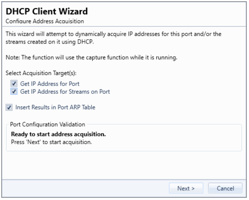
Fig. 5.14 DHCP Client Wizard - Address Acquisition
Note
Please note that if you select to acquire addresses for your streams then they must all contain an IPv4 protocol segment. If the wizard detects that this is not the case you must exit the wizard and correct this manually.
Setting SMAC for Streams
To acquire addresses for streams each stream must be configured with a unique SMAC address in the initial Ethernet protocol segment.
On initial launch the wizard will determine if the SMAC addresses for the streams are unique within the scope of the port. If not it will offer to assist you in assigning unique addresses as indicated in the Fig. 5.15 below.
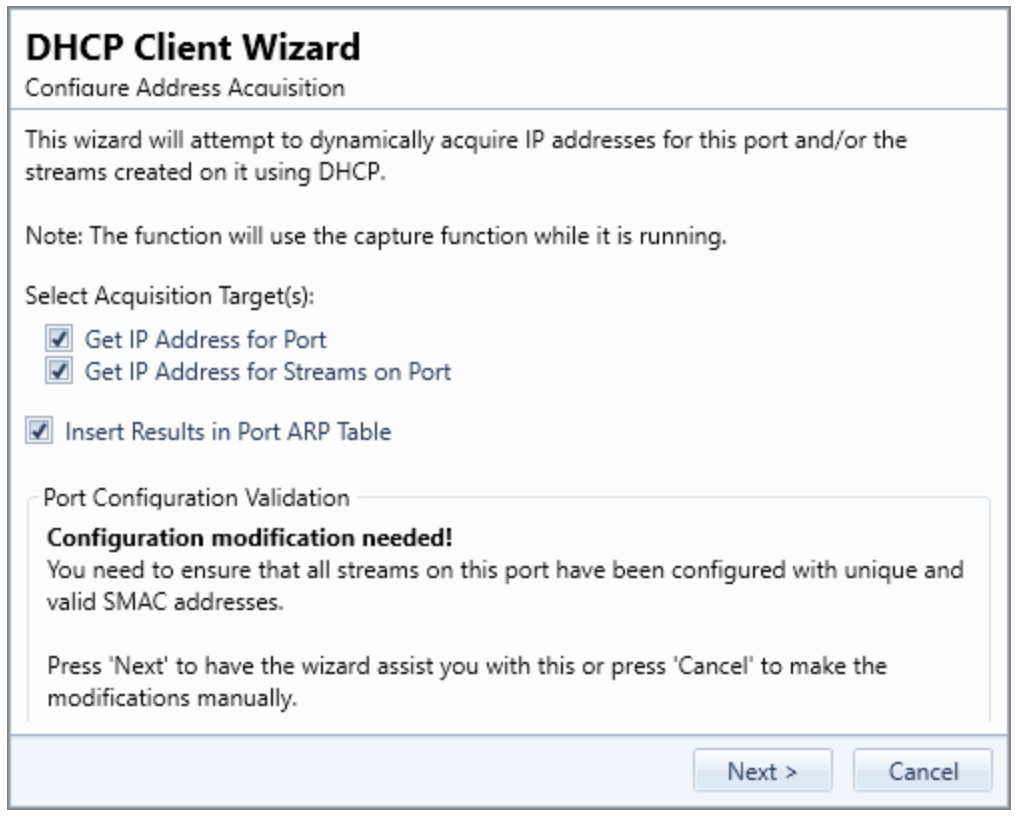
Fig. 5.15 DHCP Client Wizard - Setting SMAC
Note
Please note that the wizard will not ensure that the stream SMAC addresses are globally unique. It will only check if the SMAC addresses are unique within the scope of the port on which they reside.
Acquiring Addresses
Once all requirements are satisfied the wizard will start to acquire addresses from the DHCP server. You can follow the progress in the wizard as shown in Fig. 5.16 below.
The Counters field at the top show the number of DHCP packet sent and received. The grid below that show a summary of the communication with the DHCP server.
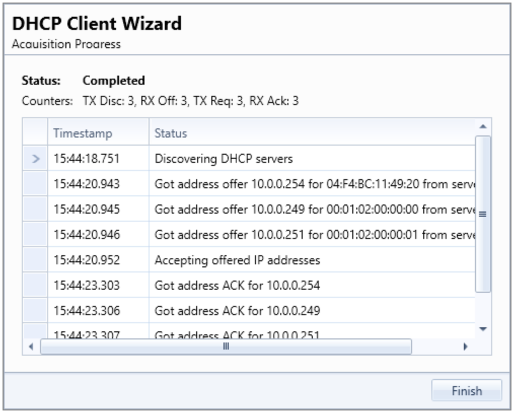
Fig. 5.16 DHCP Client Wizard - Acquiring Addresses
IPv4 Multicast Properties
Property |
Explanation |
|---|---|
MC Addresses |
Specifies a list of multicast addresses to send IGMPv2IGMPv3 requests to. |
Send Join Request |
When this button is clicked a single IGMPv2 Join request is sent to the specified multicast address. |
VLAN |
Check this box to add a VLAN tag header to sent IGMPv2IGMPv3 requests |
Tag |
Value of VLAN tag |
Priority |
Priority bits in VLAN tag header |
DEI |
Drop Eligible Indicator in VLAN tag header |
Send Requests |
For Protocol Version IGMPv2 a single request is sent when the related button is clicked. |
Send Join Request |
Send a Join Request |
Send Leave to AllRouters |
Send Leave to IP Address (224.0.0.2) |
Send Leave Request |
Send a Leave Request |
Send General Query Request |
Send a General Query Request |
Send Group Query Request |
For Protocol Version IGMPv3 a single request is sent when the related button is clicked:
|
Repeat Multicast Join |
Control whether the Join command should periodically be re-transmitted |
Multicast Join Period |
The Join retransmit period in seconds |
Protocol Version |
Set Multicast Protocol version to IGMPv2 or IGMPv3 |
Group Record Bundling |
Configure if a single membership report bundles multiple multicast group records to decrease the number of packets sent when using IGMPv3. (Only available when Protocol Version is |
IPv6 Properties
Property |
Explanation |
|---|---|
IPv6 Address |
The IPv6 network address for the port. The address is used as the default source address field in the IP header of generated stream traffic, and the address is also used for support of the NDP and PING protocols. |
IPv6 Prefix |
The IPv6 subnetwork prefix for the port, |
IPv6 Gateway |
The default IPv6 gateway address for the port. |
Reply to NDP Requests |
Control whether the port will reply to incoming NDP requests. Note When you enable this Reply to NDP Requests option, the port will reply to Neighbor Solicitation sent to both unicast and multicast addresses. See also |
Reply to PINGv6 Requests |
Control whether the port will reply to incoming PING requests |
NDP/PINGv6 Address Wildcard |
Specifies a prefix that makes the port reply to NDP/PING for the masked addresses |
ARP/NDP Address Tables
Each Xena test port contains two address tables, one for IPv4 (ARP) and one for IPv6 (NDP). Each address table can contain a number of entries. Each entry defines a set of criteria for handling incoming ARP/NDP requests. Each table can be accessed by the Edit ARP Table and Edit NDP Table buttons in this section. Pressing each button will launch a dialog as shown below
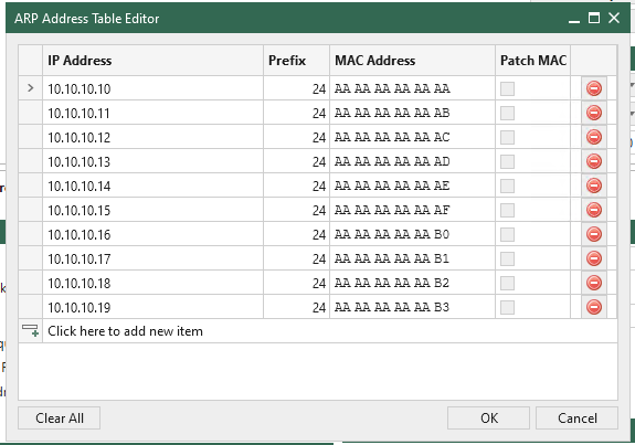
Fig. 5.17 ARP Table
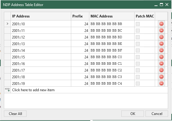
Fig. 5.18 NDP Table
New entries can be added by pressing the Click here to add new item bar. Existing entries can be edited by selecting the various fields or deleted by pressing the button with the red stop sign to the right.
Changes to the table are not sent to the test chassis until the OK button is pressed.
As an alternative you can press the Auto-Assign Tables Generate button. If you do that the content of the ARP and NDP address tables are automatically generated based on the defined streams for the port. All existing entries in the tables will be removed.
General Handling of Incoming Requests
Any incoming ARP or NDP request is handled in the following prioritized order:
If the address table for the IP version used by the request contains 1 or more entries the table is searched for a match for the Target IP Address in the request. If a match is found a reply is formatted according to the matched entry definition and sent. If no matches are found in the table the request is ignored.
If the address table for the IP version used by the request is empty the request is handled by the legacy method, i.e. matched to the defined port IP address optionally masked by the wildcard value.
Address Table Matching
Incoming ARP/NDP requests are matched to the address table by comparing the Target IP Address in the request with the IP Address value for each entry in the table, masked by the Prefix value. If a match is found the search is stopped and the matched entry used for the reply.
If two or more entries would match the Target IP Address then only the first matching entry is used.
The Prefix value can be used to have each entry match multiple IP addresses. Example: An IPv4 entry with IP Address = 10.0.0.1 and Prefix = 28 will match any address in the range 10.0.0.0 to 10.0.0.15. The default value for the Prefix is a full host mask, which means that only the specified IP address will match.
Formatting the Reply
If a match is found the ARP/NDP reply will be formatted according to the following rules:
If the MAC Address field in the match entry is all-zeros (which is the default value) the SMAC address in the reply is set to the port MAC address. Otherwise the defined MAC Address value is used.
If the Patch MAC option is checked the least significant bytes in the SMAC address is patched with the least significant bytes in the Target IP Address. Which bytes are patched is controlled by the Prefix value. This feature is relevant when using a Prefix value to reply to a range of IP addresses to ensure that each “emulated” port is returning a unique MAC address.
Port Resource Commands
This section describes the resource-specific commands available for ports in .
Property |
Explanation |
Must Reserve? |
|---|---|---|
Refresh Port |
Reload the configuration for the port and all child resources (streams, modifiers, etc) from the test chassis. |
No |
Reset Port |
Reset the port configuration to default settings. Note that this removes all dynamic resources such as streams, modifiers, etc. |
Yes |
Clear Stats |
Clear all TX and RX statistics counters on the port. |
Yes |
Start Traffic |
Start traffic on the port. The port must contain at least one enabled stream. |
Yes |
Stop Traffic |
Stop traffic on port. |
Yes |
Replay File |
Load a PCAP file and replay it on the port. This function is described in details on Replay PCAP File. |
Yes |