Packet Header Definition
This section describes the Packet Header editor used by the stream configuration pages. The editor controls the definition the protocol header segments and the associated field modifiers.
Overview
The defined protocol segments are shown in a Wireshark-like tree structure. All fields for a given segment header are shown as child rows under the segment row. Any modifiers defined on fields are shown as child rows under the field row.
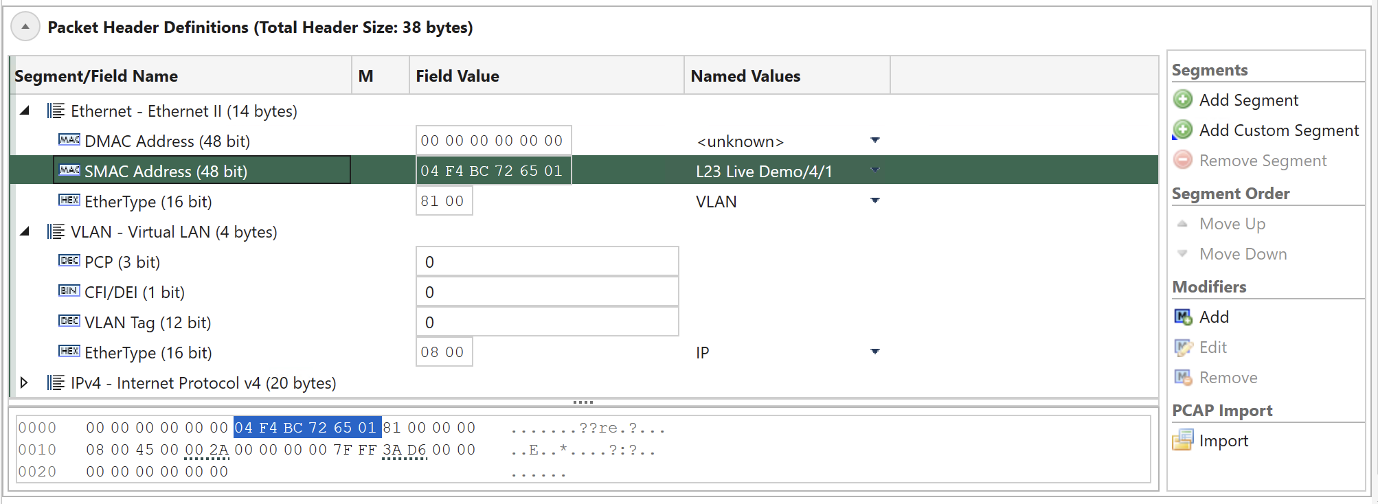
Fig. 5.105 Protocol segment profile editor
Tree Columns
The treeview contains these columns:
Column |
Explanation |
|---|---|
Segment/Field Name |
The name of the segment or field |
M |
Contains an icon that indicate if a collapsed segment or field row contains one or more modifiers. |
Field Value |
The actual field value in the common value representation for that field. |
Named Values |
Certain fields may get their value from a list of standardized or well-known named values. Instead of entering the value directly you can select the value from the dropdown list in this column. |
Field Type Icons
Each field row is prefixed with an icon indicating the value representation for the field. The following representations are used:
DEC: Decimal representation
BIN: Binary representation
HEX:Hexadecimal representation
MAC: A MAC address
IP4: An IPv4 address
IP6: An IPv6 address
Raw Hex Editor
At the bottom of the treeview you will find a raw hex editor which allow you to inspect and optionally modify the raw hex data for the segment definitions. Any changes you make in the raw editor will be written to the chassis and the associated field value controls will be updated accordingly.
When you select a segment or a field the relevant parts in the hex editor will be highlighted. The hex editor will also underline the areas affected by any defined modifier.
The left part of the hex editor contains an address list and the right part show the current raw data decoded as printable ASCII.
Segment Headers
Adding a Segment Header
To add a new segment header to the existing definition press the Add Segment button in the in the command panel to the right. You will now be presented with a list of known protocol types in alphabetical order. You can select one or more types using the standard Windows Ctrl+Click or Shift+Click operations. When you are done press the OK button.
XenaManager will check if the total size of the configured segments exceeds maximum header size and minimum packet length, and if that is the case user will be presented with a message, which will also provide the option to increase “maximum header size and minimum packet length.
Note
If a segment is removed, the maximum header size and minimum packet length are not adjusted.
Moving a Segment Header
With the exception of the first Ethernet segment you can move segment headers up or down in the list after you have added them. Select the segment you want to move and use either the Move Up or the Move Down button in the command panel to the right.
Any modifiers you have defined in segments affected by the move will be moved automatically.
Removing a Segment Header
Select the segment you want to remove and use the Remove Segment button in the command panel to the right.
Any modifiers you have defined in the removed segment will also be removed automatically.
Import From PCAP File
Instead of manually building the segment headers you can instead import the structure from a PCAP file. Note that this operation will replace any segments you may have added manually.
To import the segment structure from a PCAP file simply press the Import button in the command panel to the right and select a PCAP file on disk which contain the packet you want to import. The packets in the PCAP file will now be decoded and a list of the found packets will be shown. You should then select the packet you want to import and press the OK button.
The import function will use any trailing data in the packet as one or more custom data segments.
Note
You can download and try these PCAP sample files
Custom Segment Headers
Custom Segments resemblances to Raw Segments, but they offer the ability to customize the header structure and assign custom names to fields. This feature, known as the Custom Segment feature, lets you craft your own protocol segment, typically represented as a JSON file. This customization significantly enhances usability and tailors the segment to your specific needs.
You can define your own custom segment as the steps described below:
The new Custom segment files should be saved with
.xdefextension.The content inside these
.xdeffiles must use the JSON formatting.The
.xdeffiles must be placed inC:\Users\<username>\Documents\Xena\XenaManager\SegmentDefsClick Add Custom Segment, and you will see the added segment.
Note
You can download and try these custom segment definitions.
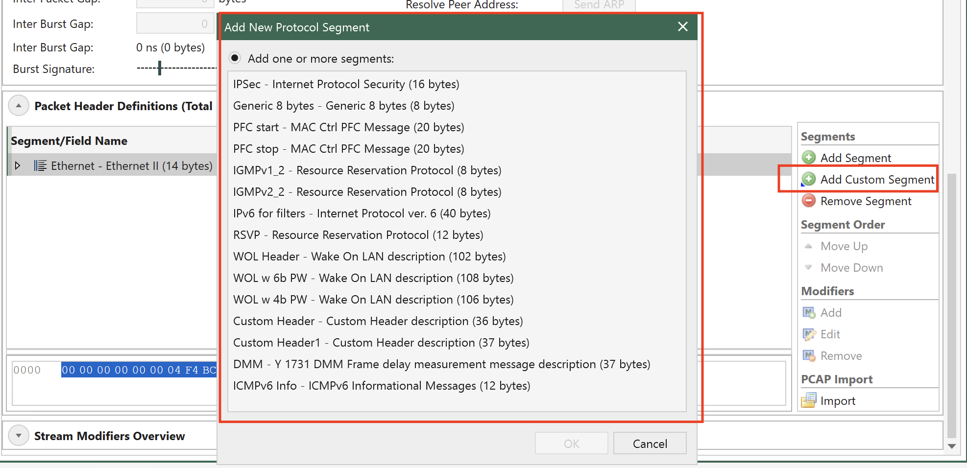
Fig. 5.106 Add Custom Segments
The JSON format of .xdef file:
{
  "Name": "Custom Header",
  "Description": "Custom Header description",
  "SegmentType": 140,               //=> accepted values range: [128 to 191]. It's a unique key, so if more than one file with same SegmentType are detected, it'll load only the first detected one
  "ProtocolFields": [               //=> array of fields for the Custom Segment, you can define as many as you need but always following JSON formatting rules
    {
      "Name": "Custom field 1",
      "BitLength": 8,
      "DisplayType": "Decimal",     //=> accepted values: [Decimal, Binary, Hex, IpV4Address, IpV6Address, MacAddress, DisplayString]
      "DefaultValue": "0"   //=> accepted values can be defined in Decimal or Hex format. Can be separated by commas with no space (,) and each value corresponds to one byte.
    },
    {
      "Name": "Custom field 2",
      "BitLength": 4,
      "DisplayType": "Binary",
      "DefaultValue": "11"  //=> decimal “11” which will be displayed binary in UI as “1011”. Maximum value in this field would be “1111” (4 bits length / “15” decimal)
    },
    {
      "Name": "Custom field 3",
      "BitLength": 2,
      "DisplayType": "Hex",
      "DefaultValue": "0xF"         //=> Valkyrie Manager will skip this value and default it to 3 as 0xF is greater than max. possible value for a 2-bit field definition (range 0-3 decimal)
    },
    {
      "Name": "Custom field 4",
      "BitLength": 16,
      "DisplayType": "Hex",
      "DefaultValue": "0xFF, 0xFF"  //=> field defined as 16 bits, so we define 2-byte default values separated by comma and in Hex format, but we can also use Decimal format
    },
    {
      "Name": "Custom field 5",
      "BitLength": 48,
      "DisplayType": "DisplayString",
      "DefaultValue": "0x48,0x65,0x6c,0x6c,0x6f,0x00" //=> field defined as 6 bytes/characters, so to define default value Decimal or Hex format of ASCII values can be used and all 6 bytes needs to be defined
    } ,
    {
      "Name": "MAC Address",
      "BitLength": 48,              //=> MAC address field's length is always 48 / 6 bytes
      "DisplayType": "MacAddress",
      "DefaultValue": "0,0,0,0,0,0"
    },
    {
      "Name": "IPv4 Addr",
      "BitLength": 32,      //=> IPv4 address field's length is always 32 / 4 bytes
      "DisplayType": "IpV4Address",
      "DefaultValue": "0,0,0,0"
    },
    {
      "Name": "IPv6 Addr",
      "BitLength": 128,     //=> IPv6 address field's length is always 128 / 16 bytes
      "DisplayType": "IpV6Address",
      "DefaultValue": "0,0,0,0,0,0,0,0,0,0,0,0,0,0,0,0"
    }
  ]
}
Setting Field Values
You can change any field value by using the associated edit control in the Field Value column. For those fields that have a set of well-known values associated you can also choose one of these values from the dropdown list in the Named Values column.
Finally you may edit the content of the fields directly in the hex editor panel if you are so inclined.
Next-Protocol Type Fields
Certain protocol segment types (such as Ethernet, VLAN and IP) contain fields that indicate the type of the next segment. The segment editor will attempt to set such fields to a correct value when you add, remove or move segments. You can however override the value afterwards if necessary.
Modifiers
Modifiers are specified directly on the field hey are supposed to modify.
Adding Modifier
To add a modifier select the field you want to modify and click the Add button in the Modifiers section in the command panel to the right. You will now be presented with a window allowing you to specify the properties for the modifier. Press the OK button when you are done.
The new modifier will be shown as a child row under the field row. The value in the Field Value column is a read-only string representation of the modifier settings.
Editing Modifier
To edit the properties of an existing modifier select the modifier and click the Edit button in the Modifiers section in the command panel to the right.
Removing Modifier
To remove a modifier select the modifier and click the Remove button in the Modifiers section in the command panel to the right.
Modifier Endianness
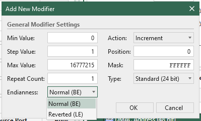
Fig. 5.107 Configure modifier endianness
The endianness of a modifier is specified in the modifier editor. The endianness is used to determine how the modifier value is applied to the field value. The endianness can be set to either Normal (BE) or Reverted (LE).
Normal (BE) means that the modifier inc/dec the field value from the LSB (Least Significant Bit) to the MSB (Most Significant Bit).
Reverted (LE) means that the modifier inc/dec the field value from the MSB to the LSB, as shown in the illustration below.
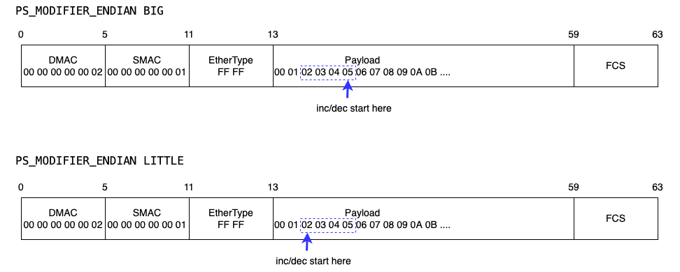
Fig. 5.108 Modifier endianness illustration