Transceiver Features
This section only applies to ports that support direct access to their transceiver through a well-defined register interface such as the MII register interface.
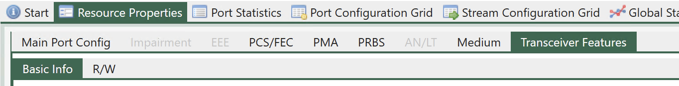
Fig. 5.66 Port Properties - Transceiver features
This function is mainly provided for debugging purposes and will normally not be required for ordinary test usage.
Basic Info
Basic Info tab panel provides basic transceiver information summary. The information on this page is obtained from reading management interface of the transceiver and may not necessarily be the same as what is indicated in its data sheet.
Read Table Info
On-demand read and auto-refresh.
Clicking Read button trigger an on-demand read the transceiver memory.
If you need to periodically refresh, you can enable auto-refresh by enabling Auto Refresh with a polling interval in seconds.
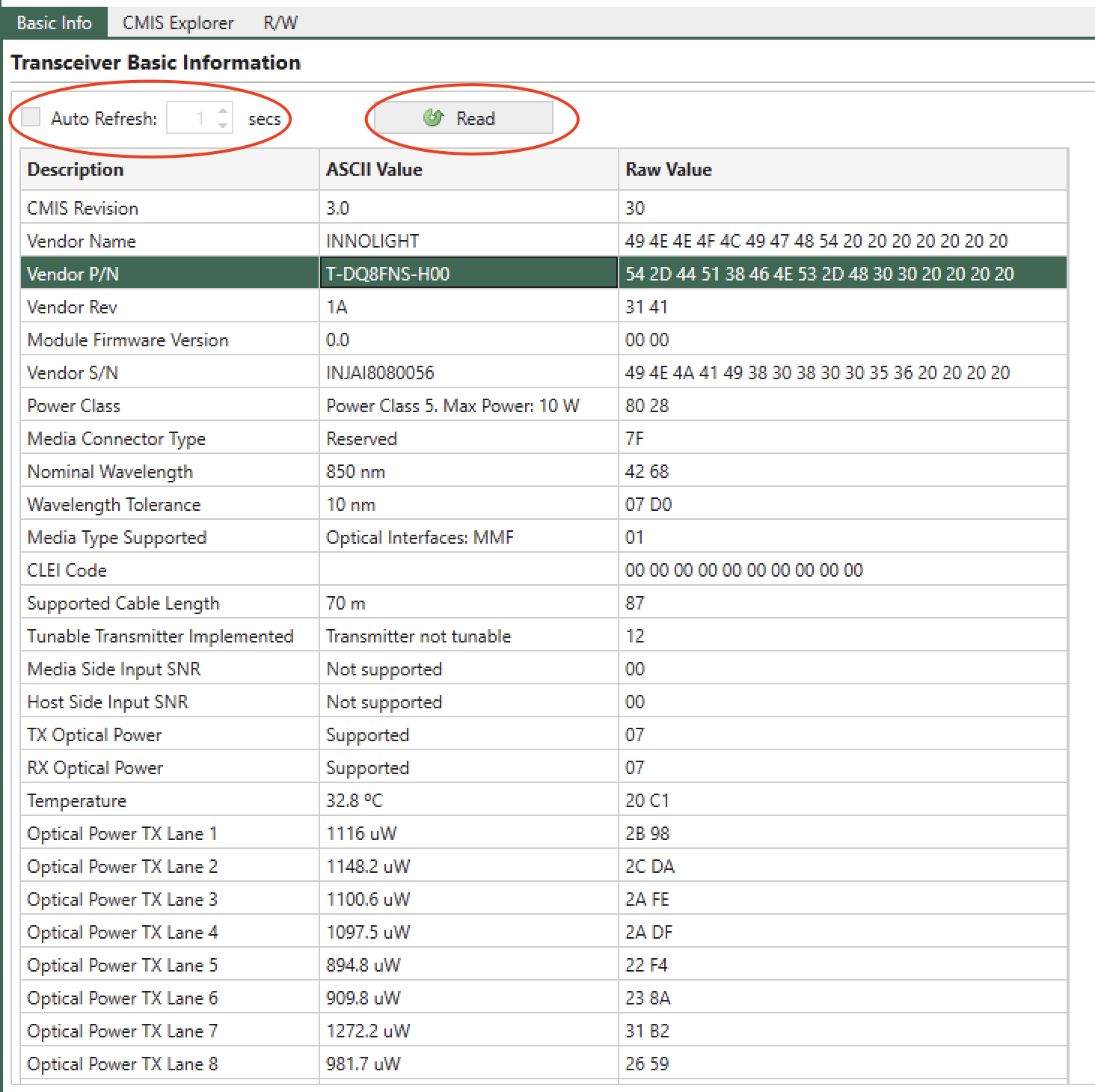
Fig. 5.67 Basic Info Table
Important
The GUI only reads the transceiver memory when you click the tab. Clicking on a port doesn’t trigger a read operation on the transceiver. This is sometimes useful when you don’t want the GUI to interrupt your operations on the transceiver.
Search
The Basic Info table allows you to search the description by Ctrl-F, as shown below.
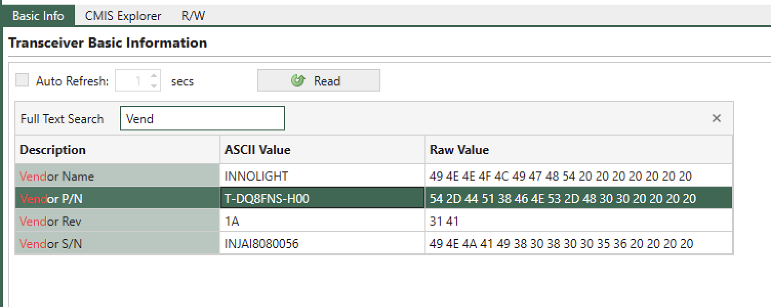
Fig. 5.68 Basic Info Table Search Bar
CMIS Explorer
CMIS Explorer provides a fully customizable memory byte view of the transceiver memory that is plugged in the socket cage. CMIS Explorer can be found under .
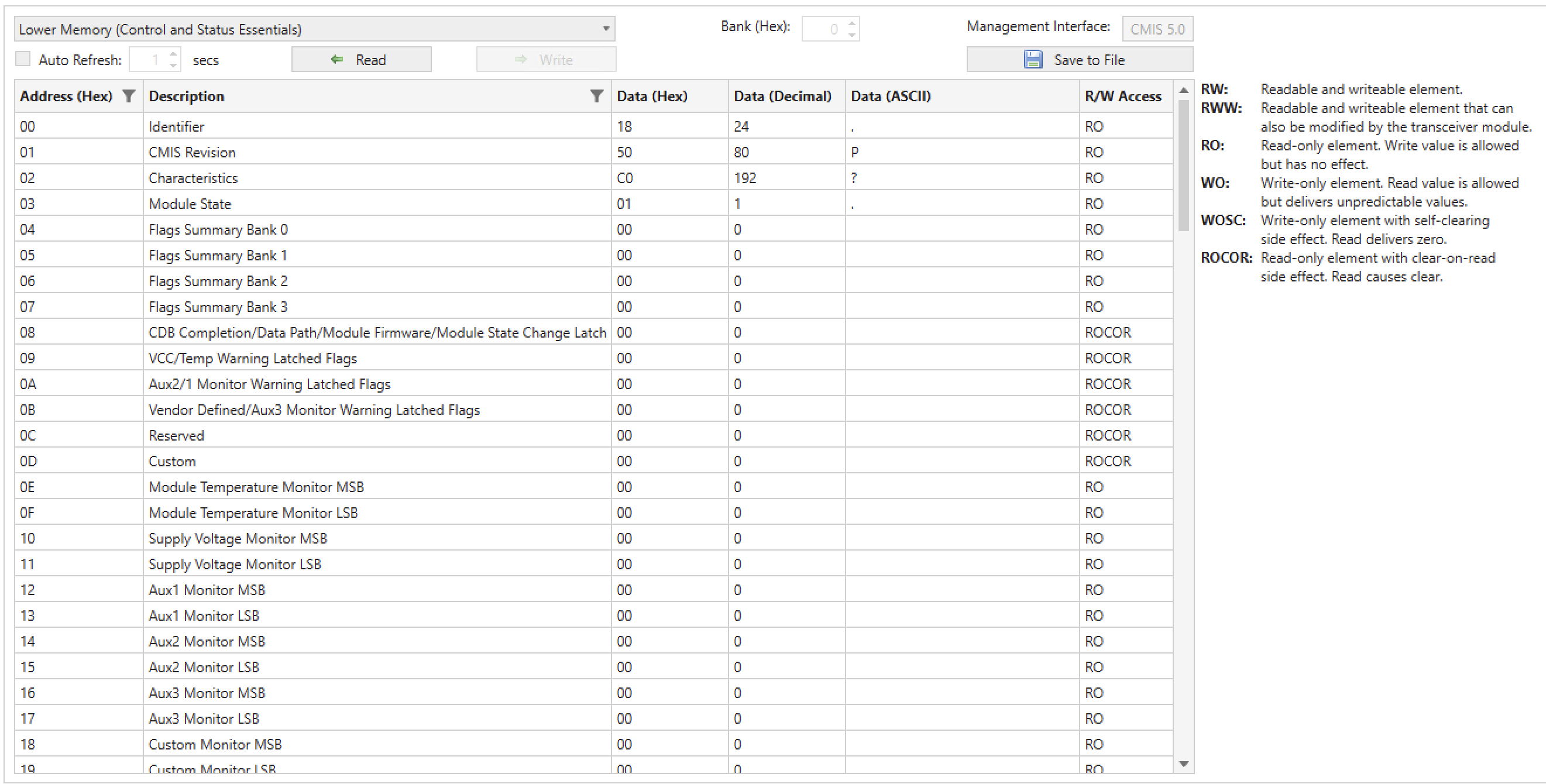
Fig. 5.69 CMIS Explorer Overview
Customization
The CMIS Explorer allows you to customize the transceiver memory page definitions. You can:
Decide which page to display, allowing you to make your own byte viewer.
Specify which bytes on a page to show, helping you concentrate on the bytes you work with.
Change descriptions for both pages and bytes, which is very useful when you want to remember the the use of some particular bytes on a page.
When you launch XenaManager for the first time, the application creates a folder at C:\Users\username\Documents\Xena\XenaManager\TcvrCmisDefs and generates a CMIS page definition JSON file for each page according to the CMIS specification. Consequently, there are 257 definition files for each CMIS specification. These definition files are used by XenaManager to populate the CMIS page selection drop-down list.
When you want to customize a page, simple go to the corresponding folder and open the corresponding JSON file for that page, as shown in Fig. 5.70.
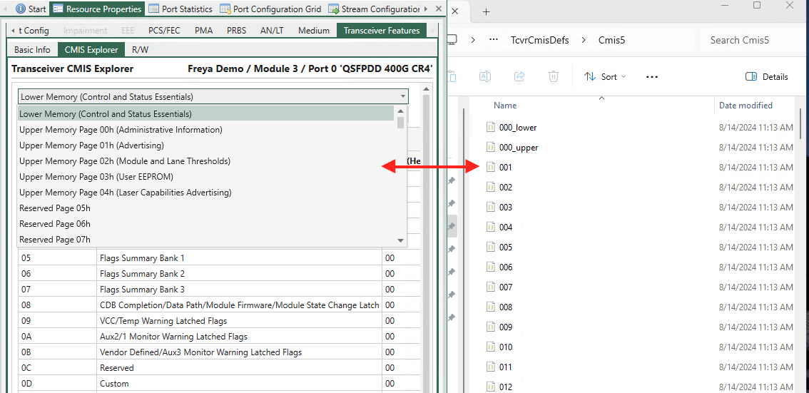
Fig. 5.70 Customize a page in CMIS Explorer
You can change the following values in the definition JSON files as shown in Fig. 5.71.:
page_description: this is the page name shown in the drop-down selection listreg_list: this list contains the bytes you want the CMIS Explorer to show on this pagedescription: this is the description of the byteaddress: address of the byte
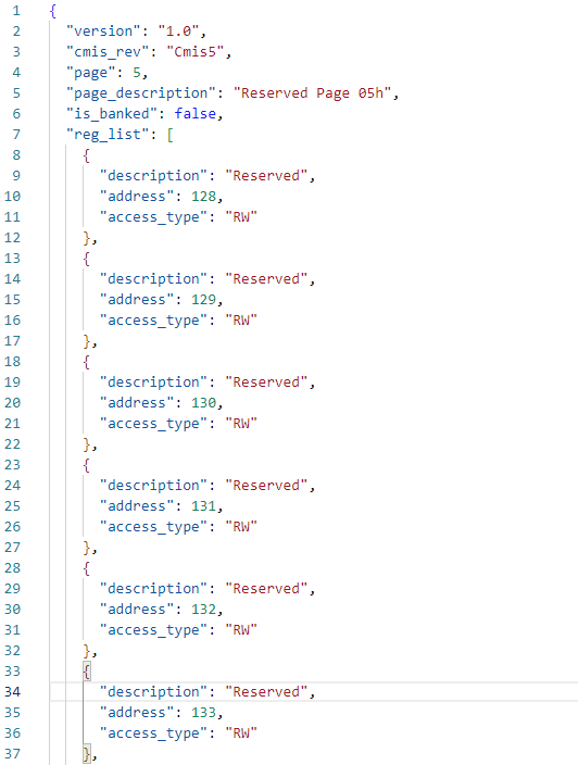
Fig. 5.71 Definition file in JSON format
Important
It is highly recommended that you save a copy of the entire C:\Users\username\Documents\Xena\XenaManager\TcvrCmisDefs folder before you customizing the CMIS Explorer. This is because XenaManager doesn’t provide the undo feature.
Note
If a subfolder in C:\Users\username\Documents\Xena\XenaManager\TcvrCmisDefs cannot be found when XenaManager is launched, XenaManager will regenerate the default definition files for that subfolder.
For example, if C:\Users\username\Documents\Xena\XenaManager\TcvrCmisDefs is missing, XenaManager will generate C:\Users\username\Documents\Xena\XenaManager\TcvrCmisDefs and its default definition files. If the subfolder is not empty, XenaManager will not change any file in it.
Page Selection
Use the page selection drop-down list to select the page you want to view.
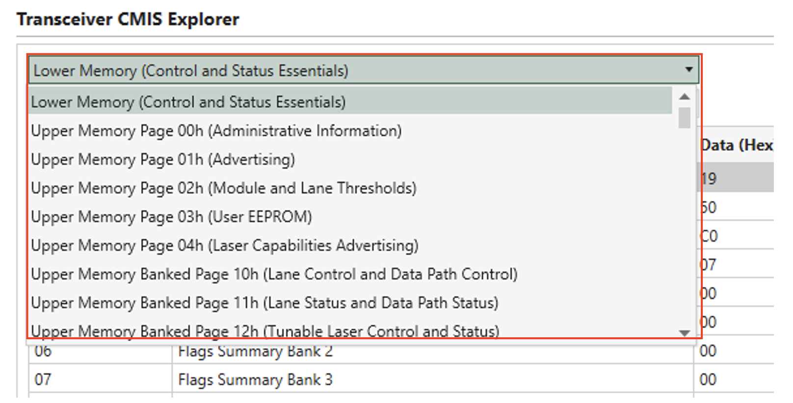
Fig. 5.72 Page Selection
Bank Selection
Bank selection (for banked pages). Use the Bank (Hex) stepper field to select the bank.
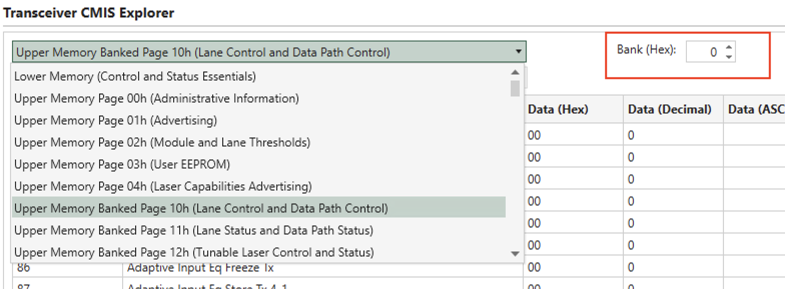
Fig. 5.73 Bank Selection
Management Interface
View the CMIS specification version of the transceiver in Management Interface.
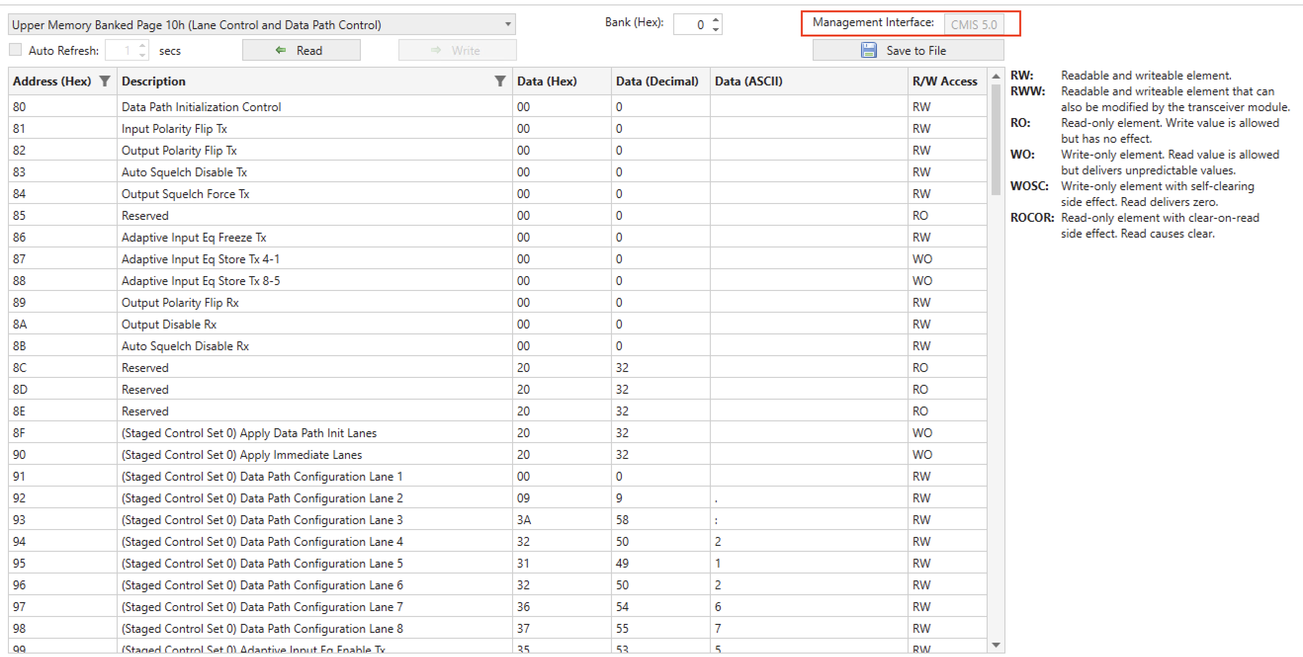
Fig. 5.74 Management Interface
Description Column
Description of each byte.
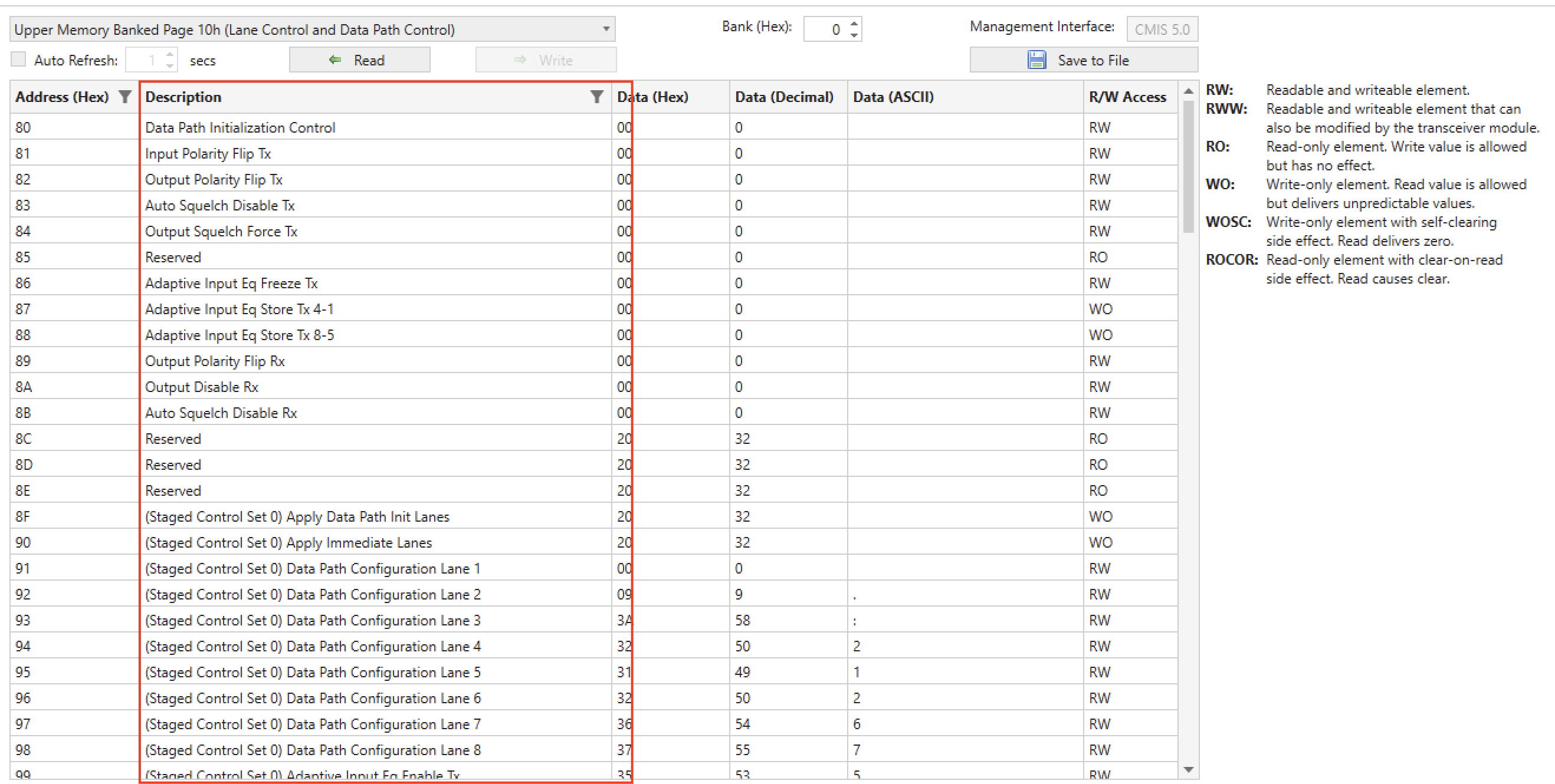
Fig. 5.75 Byte Description
Value Columns
Each table row corresponds to a byte on the page. The value of a byte is presented in three columns:
Data (Hex): raw binary value of the byte in hex format.
Data (Decimal): decimal format of the byte value.
Data (ASCII): ASCII format of the byte value.
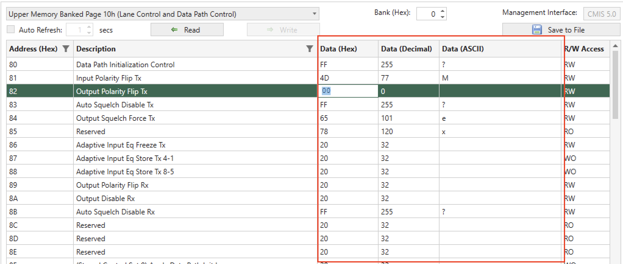
Fig. 5.76 Byte Value
Read Values
On-demand read and auto-refresh.
Clicking Read button trigger an on-demand read of all the bytes of the selected page/bank.
If you need to periodically monitor the page/bank, you can enable auto-refresh by enabling Auto Refresh with a polling interval in seconds.
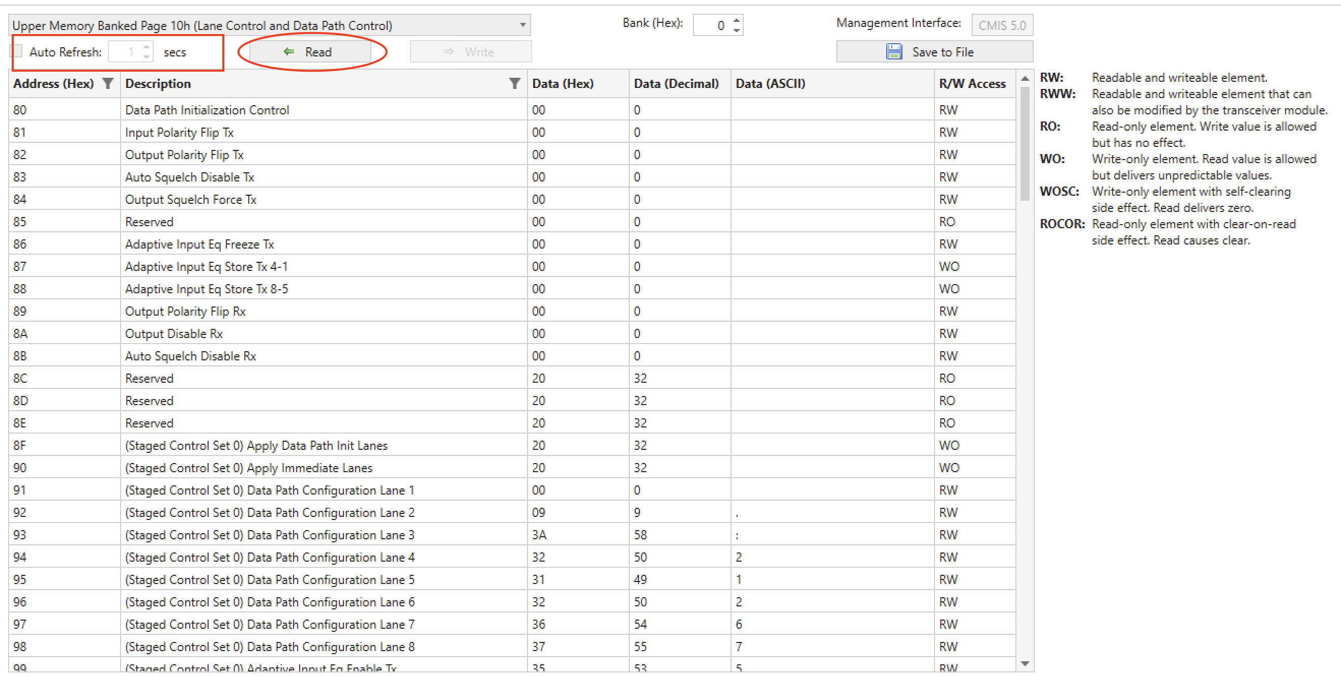
Fig. 5.77 Read Values
Write Values
Write values into register bytes. Click on the cells in Data (Hex) or Data (Decimal) to enter the corresponding value you want to write.
Click the Write button to commit the write changes. This allows you to batch write into the page/bank of the transceiver.
Attention
Writing into RO bytes is allowed but the value will be ignored by the transceiver.
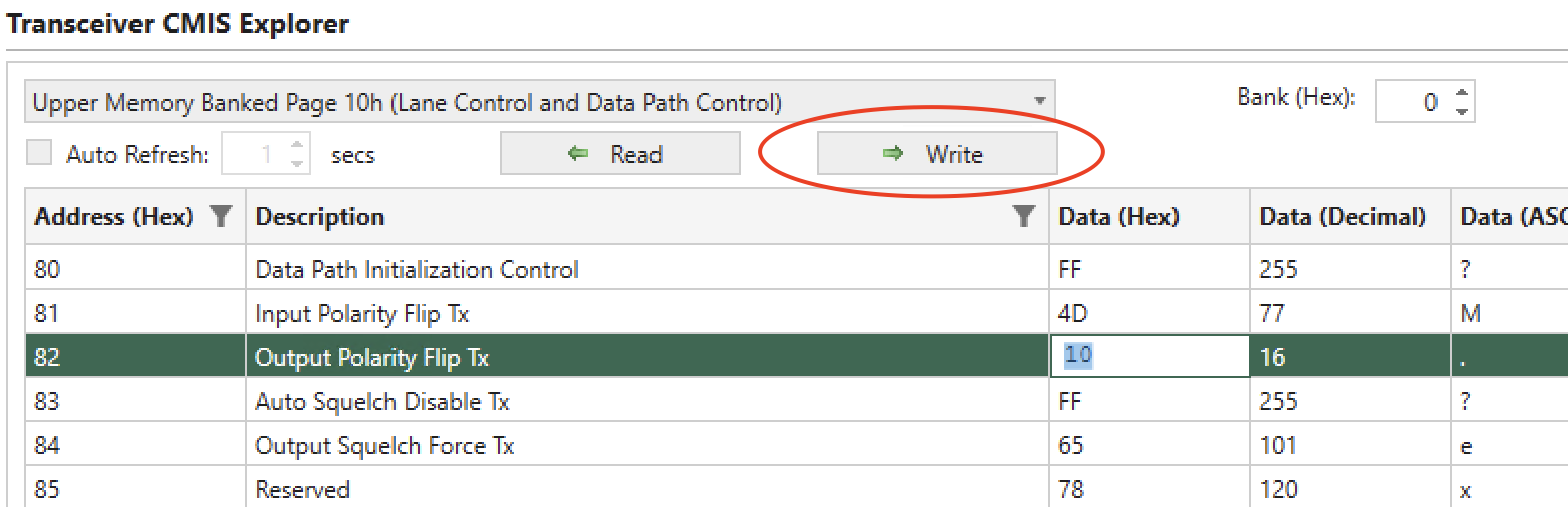
Fig. 5.78 Write Values
R/W Access
The CMIS Explorer shows the read/write access level of each byte.
R/W Access |
Description |
|---|---|
RW |
A readable and writeable element. |
RWW |
A readable and writeable element that can also be modified by the module. |
RO |
A read-only element. A WRITE of a value to a read-only element is allowed but has no effect. |
WO |
A write-only element. A READ from a write-only element is allowed but delivers unpredictable values. |
WOSC |
A write-only element with self-clearing side effect. A READ from a WO/SC element is allowed and delivers a zero value, except transiently when reading before the module has evaluated and cleared the non-zero bits written. |
ROCOR |
A read-only element with clear-on-read (clear-after-read) side effect. All bits in a RO/COR Byte are cleared by the module after the Byte value has been read. |
Save This Page
Save selected the page/bank into a csv file. Click Save This Page button to save the entire page into a csv file, including all information shown in the displayed table.
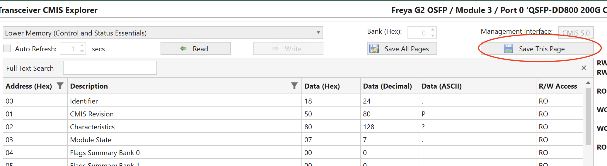
Fig. 5.79 Save This Page
Save All Pages
When you click Save All Pages in , XenaManager will save the register values of all pages from the drop-down list. Each page’s data is saved into a separate CSV file.
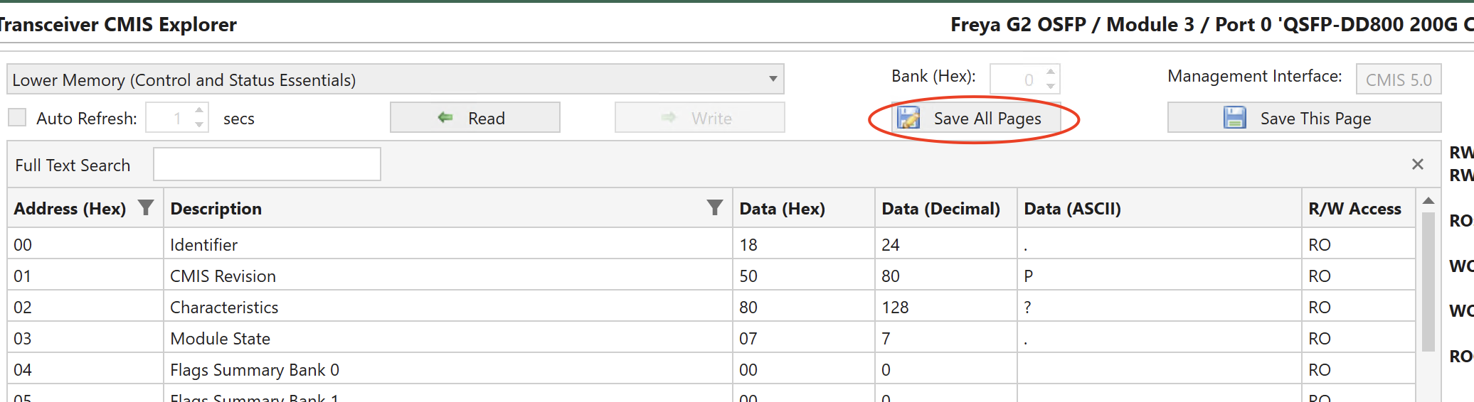
Fig. 5.80 Save All Pages
The saving process takes 2-3 minutes depending on the number of pages in the drop-down list.
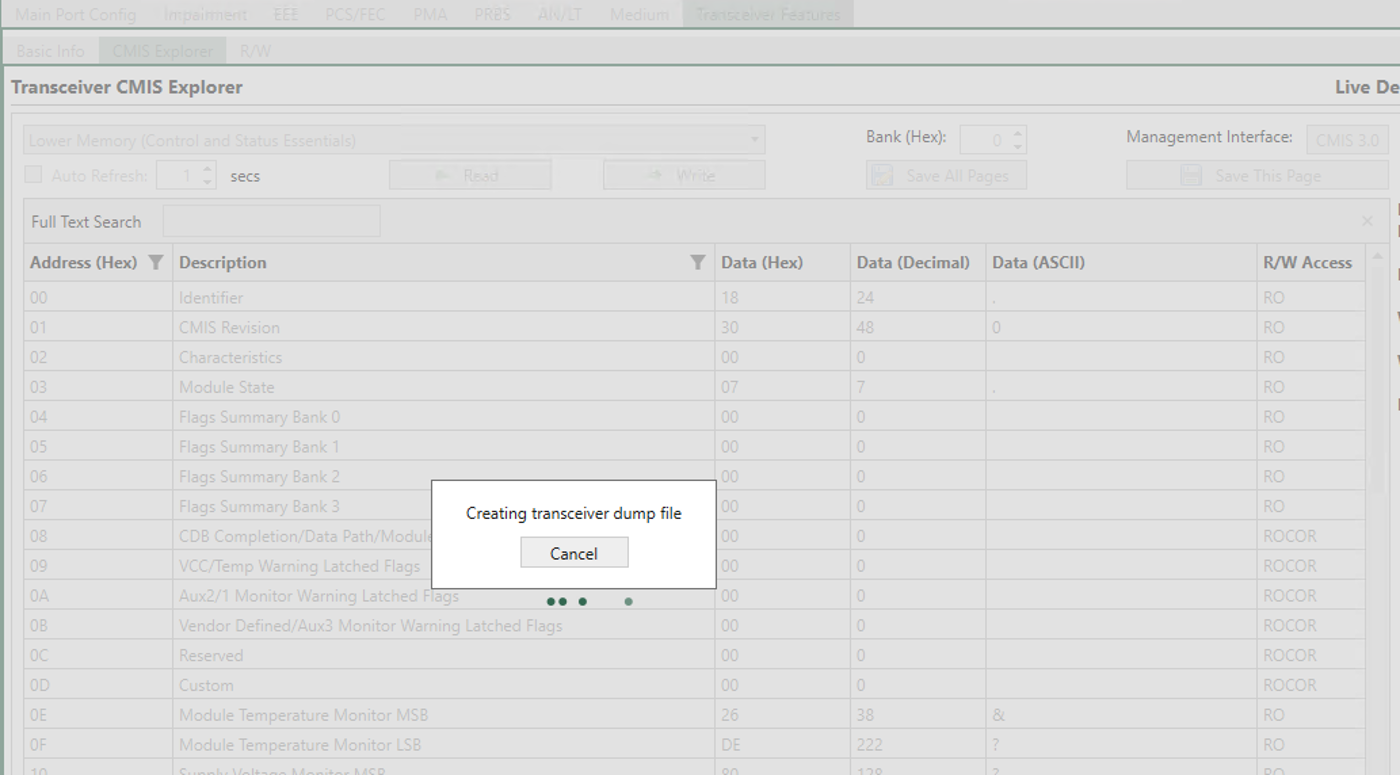
Fig. 5.81 The process of saving all pages takes 2-3 minutes depending on the how many pages are in the drop-down list.
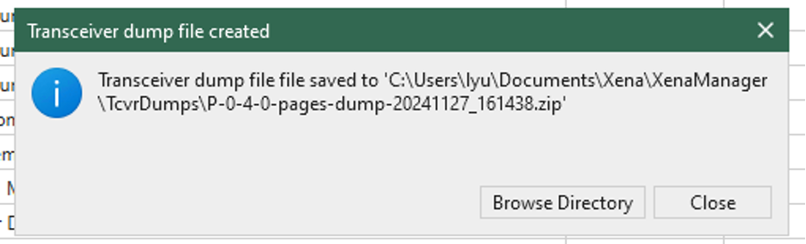
Fig. 5.82 When saving is done, the path to the saved zip file is provided.
Search Bar
The CMIS Explorer table allows you to search the byte description using the search bar. By default the search bar is enabled. To bring back a closed search bar, use Ctrl-F.
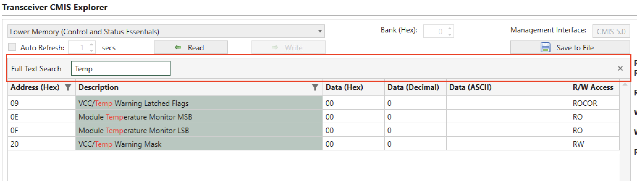
Fig. 5.83 CMIS Explorer Search Bar
Supported CMIS Specification
CMIS Explorer supports the following CMIS specifications:
CMIS 3.0
CMIS 4.0
CMIS 5.0
CMIS 5.1
CMIS 5.2
Important
The GUI only reads the transceiver memory when you click the tab, or changing page/bank. Clicking on a port doesn’t trigger a read operation on the transceiver. This is sometimes useful when you don’t want the GUI to interrupt your operations on the transceiver.
R/W
R/W tab panel allows you to directly read and write to the transceiver register.
I2C Access Speed Configuration
The I2C RX/TX transceiver access speed on the Z400 Thor 112G PAM4 can now be configured, enabling an increase in the I2C access speed to a maximum of 800KHz. This enhancement facilitates quicker diagnostics and firmware updates among other tasks involving transceivers.
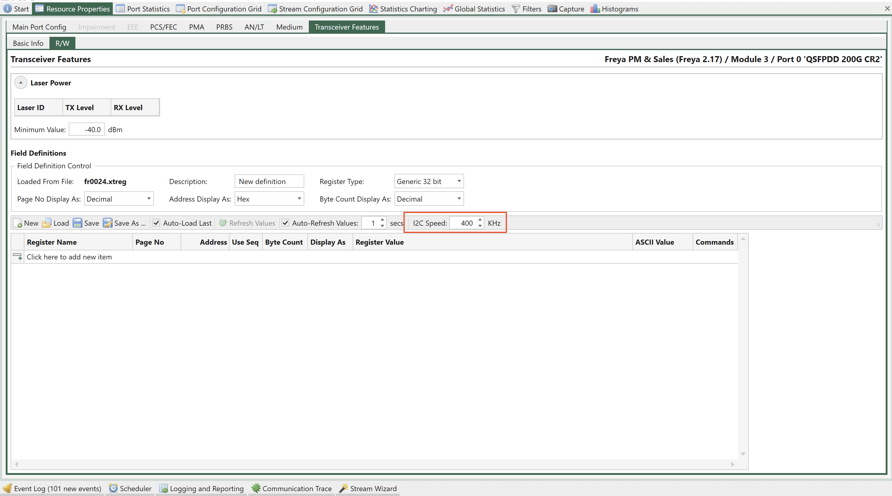
Fig. 5.84 Port Properties - I2C access speed configuration
Laser Power
In addition to register access the The Transceiver Features panel can show laser power information if that is supported by the module and the port transceiver.
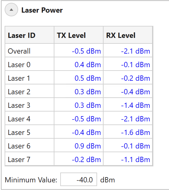
Fig. 5.85 Port Properties - Laser power
TX and RX power level will be shown for each laser in the transceiver together with an overall reading, which shows the lowest values for the displayed power levels. You can set a Minimum value: If any you the level readings are below the Minimum value they will be highlighted with a red color.
Register Access
The Transceiver Features panel provides access to the register interface supported by the port transceiver. It is possible to both read and write register values.
All supported registers for a transceiver are shown in Fig. 5.86.
All registers for a given transceiver type is typically organized in sets called pages. Each register within a given page is then identified by an address.
It is possible to read consecutive addresses from a page using sequential access by ticking Use Seq and configure byte count.
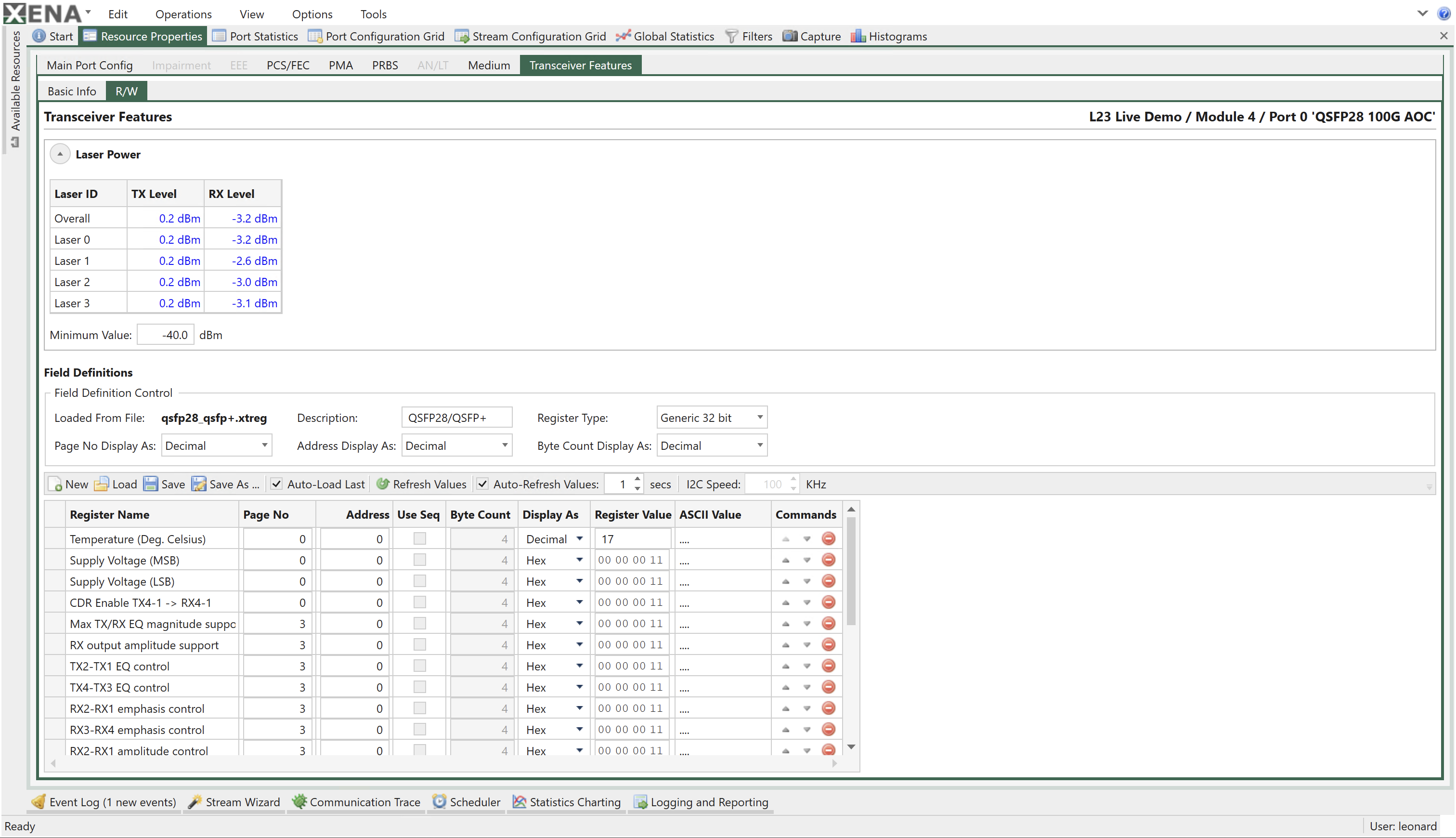
Fig. 5.86 Port Properties - Register access
Reading Register Values
The register values can be read manually by pressing the Refresh Values in the panel toolbar. The panel can also refresh the values periodically if the Auto-Refresh option is enabled.
The field values will primarily be displayed using the selected field display type (hex, decimal or binary) but it will also be displayed as ASCII characters for convenience.
Writing Register Values
The register values may also be changed by the user by changing the value in the Register Value column. The new value is applied when the Enter key is pressed.
It is not possible to change the ASCII character value directly.
Register Definitions
Each set of supported register fields for a given transceiver type is defined in a separate file with extension .xtreg. The data definition is formatted using JSON notation.
You can load a register definition file by pressing the Load button ion the toolbar. If the Auto-Load Last option is selected then the last loaded definition will automatically be loaded the next time XenaManager is started.
Built-in Register Definitions
The XenaManager is shipped with a set of commonly used register definitions, such as the MII register set mentioned above. These files will be kept in the folder Documents\Xena\XenaManager\TcvrDefs.
Creating or Modifying Definitions
It is also possible to modify the built-in register definitions or create your own from scratch.
To create a new definition you should press the New button in the toolbar. You can also change an existing definition by loading it and saving it under a new name.
Changing Display Options
The top subpanel called Field Definition Control defines the overall handling of all register fields in the definition. You can change the display type (hex or decimal) of both address and page number fields. You can also change the bit width (16 or 32 bit) of the register addresses.
Adding or Removing Fields
You can add a new register field by pressing the area at the bottom of the field definition table labeled Click here to add a new item. The new item will be added to the bottom of the table.
You can reorder the field by using the up- and down-arrows in the Commands column.
To remove a field press the Delete icon in the Commands column.