5.3.5. Stream Properties
This section describes the available stream properties for XenaManager.
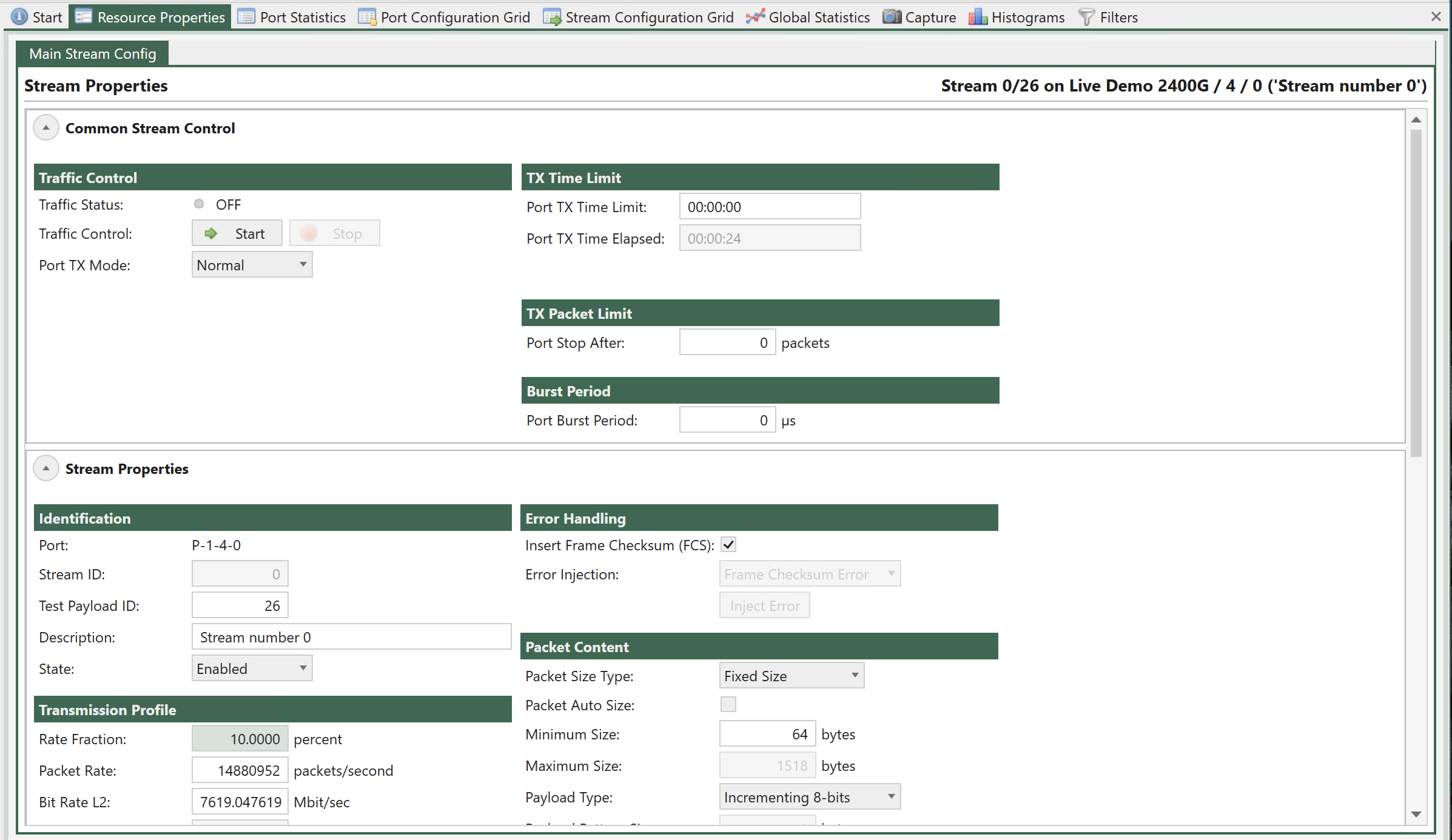
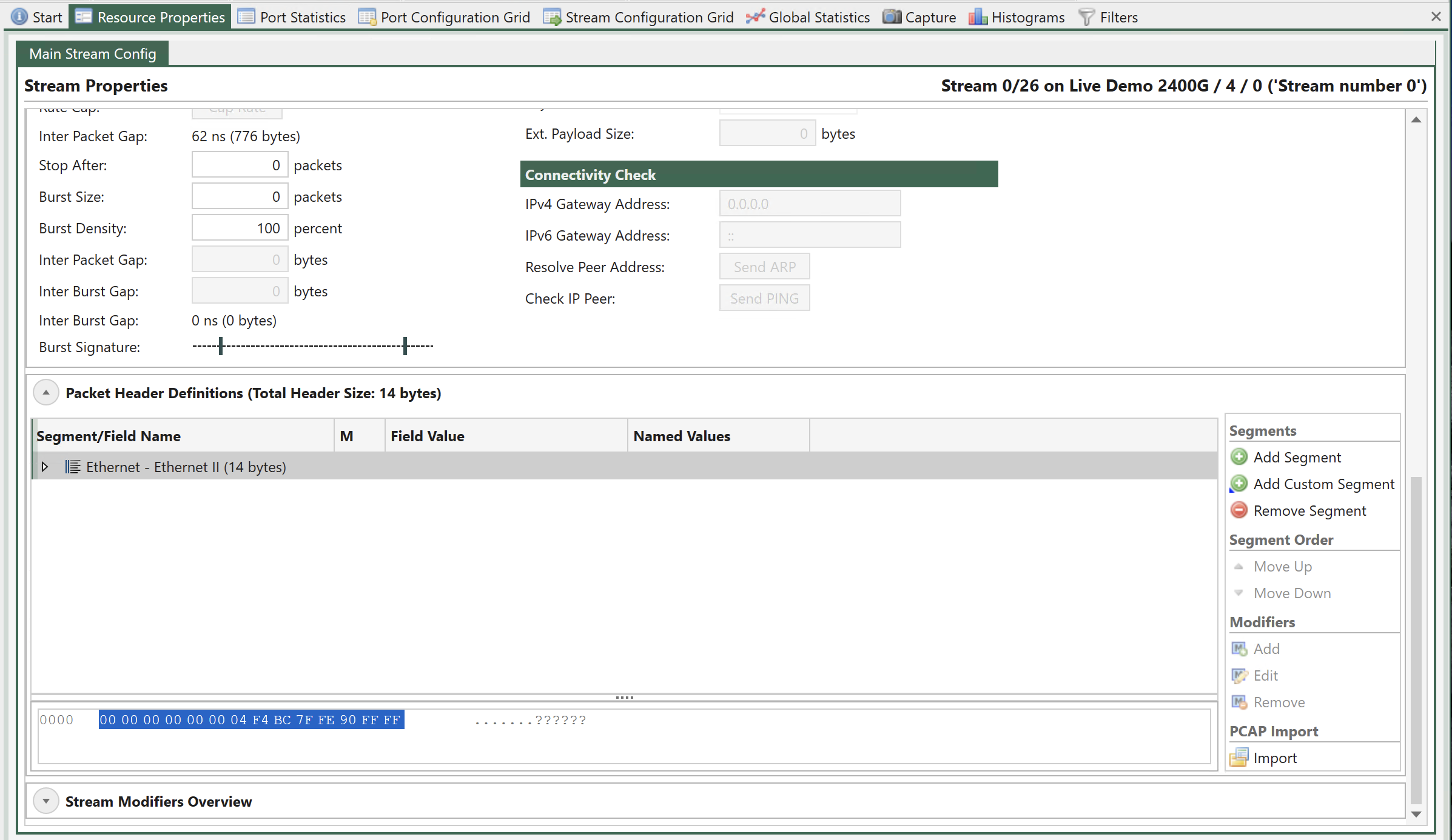
Fig. 5.87 Stream Properties
Common Stream Control
This area contains port-level controls that affect all streams on that port. They are shown on the streams property page for the sake of convenience.
Traffic Control
Property |
Explanation |
|---|---|
Traffic Status |
The current traffic status for the port (OFF: traffic is off, ON: traffic is on) |
Traffic Control |
This button enables you to either start or stop traffic on the port |
Port TX Mode |
This property determines the scheduling mode for outgoing traffic from the port, i.e. how multiple logical streams are merged onto one physical port. Refer to CLI command - P_TXMODE for further information. |
Port Stop After |
Stop port transmission after the specified number of packets are sent |
Port Burst Period |
Time in micro seconds from start of sending a group of bursts till start of sending next group of bursts |
TX Time Limit
Property |
Explanation |
|---|---|
Port TX Time Limit |
The maximum time the port should transmit |
Port TX Time Elapsed |
The amount of time the port has been transmitting. |
Main Properties
This area contain all stream-level configuration properties, except those related to protocol header and modifier definitions.
Identification
Property |
Explanation |
|---|---|
Port |
The parent port name |
Stream ID |
The unique stream ID |
Test Payload ID |
The test payload ID (TID) carried in the Xena test payload area. This field can be empty if no TID value is needed. |
Description |
A user-modifiable description label for the stream |
State |
The stream enable state. |
Transmission Profile
Property |
Explanation |
|---|---|
Rate Fraction |
The stream traffic rate expressed as a percentage of the effective rate for the port. |
Packet Rate |
The stream traffic rate expressed as packets per second. |
Bit Rate L2 |
The stream traffic rate expressed as bits per second seen on Layer 2. |
Bit Rate L1 |
The stream traffic rate expressed as bits per second seen on Layer 1. |
Rate Cap |
This command can be used to cap the rate for disabled streams. The button will only be enabled if the sum of the defined stream bandwidth actually exceeds the available port bandwidth. |
Inter Packet Gap |
The calculated mean inter-packet gap with the current TX profile settings. This denotes the space between the end of the preceding packet and the start of the following packet. |
Seq.Packets |
The number of sequential packets sent before switching to the next stream (packets). This property is only configurable when the Port TX Mode is set to Sequential. |
Stop After |
Stop stream transmission after the specified number of packets are sent. This value can be empty or zero, which means that the stream will continue to transmit until traffic is stopped at the port level. The Stop after function is not an option when Port TX Mode is set to Sequential. |
Burst Size |
The number of packets in each burst (packets). Valid range 0-500
|
Burst Density |
The density of the burst expressed as a percentage value between 0 and 100.
|
Inter Packet Gap |
Gap between packets in a burst.
|
Inter Burst Gap |
Gap between the burst from this stream and the burst from the next stream.
|
Inter Burst Gap |
The calculated inter-burst gap with the current burst settings. This denotes the space between the end of the last packet in the preceding burst and the start of the first packet in the following burst. |
Burst Signature |
A graphical depiction of the current burst settings |
Refer to the Fig. 5.88 below for an illustration of the burst mode.
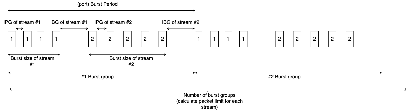
Fig. 5.88 Port TX Burst Mode
Error Handling
Property |
Explanation |
|---|---|
Insert Frame Checksum (FCS) |
Control if a valid frame checksum is added to the stream packets. Default is enabled. |
Error Injection |
Specifies the type of error that is injected into the traffic stream. The following types of errors can be specified:
It is only possible to inject errors on a stream if traffic is active on the parent port. |
Inject Error |
Inject a single error of the specified type into the traffic stream. This option is only enabled when traffic is active on the parent port. |
Packet Content
Property |
Explanation |
|---|---|
Packet Size Type |
The size distribution of the packets transmitted for the stream Important Read how to generate mixed packet size in MIX Weights. |
Packet Auto Size |
If selected XenaManager minimum packet size is auto adjusted so it equals the configured packet size in the stream. |
Minimum Size |
The lower limit of the packet size (if required by the size type) |
Maximum Size |
The upper limit of the packet size (if required by the size type) |
Payload Type |
The type of payload data used in the Xena payload section.
Important When using Incrementing 16-bit or Decrementing 16-bit, you need to check the option Payload Start From 0 to have the payload 00 00 00 01 00 02 00 03 00 04 00 05 … or FF FF FF FE FF FD FF FC FF FB FF FA…. |
Payload Pattern |
The pattern of bytes to be repeated when the type is set to Pattern. |
Payload Pattern Size |
When choosing Pattern as Payload Type, it is possible to define the size of the repeated payload pattern part. |
Ext. Payload Size |
The size of the extended payload if this option has been enabled on the parent port. Refer to Freely Programmable Test Packets (Custom Data Fields) for details. |
Connectivity Check
Property |
Explanation |
|---|---|
IPv4 Gateway Address |
The IPv4 gateway address used to resolve the DMAC address for the stream. Only valid if the stream contains an IPv4 protocol segment. |
IPv6 Gateway Address |
The IPv6 gateway address used to resolve the DMAC address for the stream. Only valid if the stream contains an IPv6 protocol segment. |
Resolve Peer Address |
Send an ARP or NDP request to the peer in order to resolve the MAC address. Only valid of an IPv4 or IPv6 segment has been defined with a valid Dest. IP address is defined. |
Check IP Peer |
Send a PING request to the peer in order to check the connectivity. Only valid of an IPv4 or IPv6 segment has been defined with a valid Dest. IP address is defined. |
The Xena tester will set the Target IP Address in any ARP/NDP request sent from a Xena test port to a value in the following prioritized order:
Stream gateway IP address for the IP version used by the stream if defined.
Port gateway IP address for the IP version used by the stream if defined and stream Dest IP Address is not in same subnet as the port gateway (the legacy method).
Stream Dest. IP Address
Important
You can create multiple IPv4/IPv6 streams on a port to simulate traffic from multiple IPv4/IPv6 client endpoints behind a physical port. Each endpoint can have different source MAC addresses and source IP addresses. At this point, the MAC address of the physical test port become unimportant for testing because it is the “virtual clients” behind that matter. However, to make each “virtual client” successfully resolve the destination’s MAC address (either the gateway or the destinations), you must configure (or auto-generate) the port’s ARP/NDP Address Tables accordingly by clicking the Generate in Main Port Config
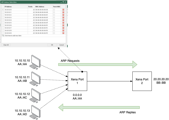
Fig. 5.89 Generate ARP/NDP table for the port in order to successfully do ARP/NDP resolution for streams
Packet Header Definition
This section describes the Packet Header editor used by the stream configuration pages. The editor controls the definition the protocol header segments and the associated field modifiers.
Overview
The defined protocol segments are shown in a Wireshark-like tree structure. All fields for a given segment header are shown as child rows under the segment row. Any modifiers defined on fields are shown as child rows under the field row.
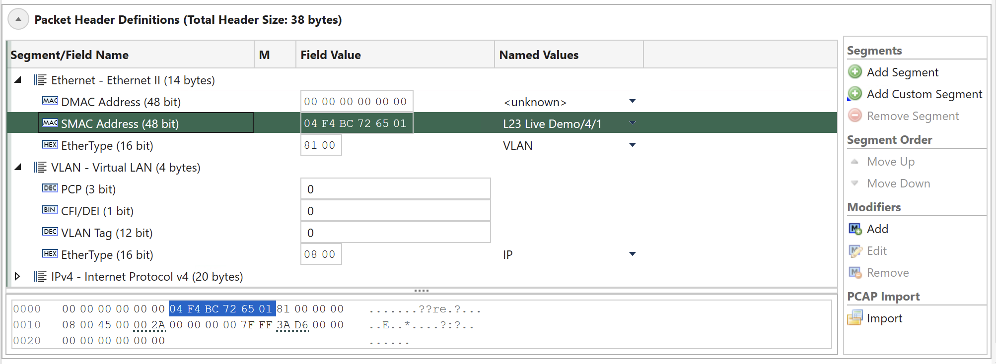
Fig. 5.90 Protocol segment profile editor
Tree Columns
The treeview contains these columns:
Column |
Explanation |
|---|---|
Segment/Field Name |
The name of the segment or field |
M |
Contains an icon that indicate if a collapsed segment or field row contains one or more modifiers. |
Field Value |
The actual field value in the common value representation for that field. |
Named Values |
Certain fields may get their value from a list of standardized or well-known named values. Instead of entering the value directly you can select the value from the dropdown list in this column. |
Field Type Icons
Each field row is prefixed with an icon indicating the value representation for the field. The following representations are used:
DEC: Decimal representation
BIN: Binary representation
HEX:Hexadecimal representation
MAC: A MAC address
IP4: An IPv4 address
IP6: An IPv6 address
Raw Hex Editor
At the bottom of the treeview you will find a raw hex editor which allow you to inspect and optionally modify the raw hex data for the segment definitions. Any changes you make in the raw editor will be written to the chassis and the associated field value controls will be updated accordingly.
When you select a segment or a field the relevant parts in the hex editor will be highlighted. The hex editor will also underline the areas affected by any defined modifier.
The left part of the hex editor contains an address list and the right part show the current raw data decoded as printable ASCII.
Segment Headers
Adding a Segment Header
To add a new segment header to the existing definition press the Add Segment button in the in the command panel to the right. You will now be presented with a list of known protocol types in alphabetical order. You can select one or more types using the standard Windows Ctrl+Click or Shift+Click operations. When you are done press the OK button.
XenaManager will check if the total size of the configured segments exceeds maximum header size and minimum packet length, and if that is the case user will be presented with a message, which will also provide the option to increase “maximum header size and minimum packet length.
Note
If a segment is removed, the maximum header size and minimum packet length are not adjusted.
Moving a Segment Header
With the exception of the first Ethernet segment you can move segment headers up or down in the list after you have added them. Select the segment you want to move and use either the Move Up or the Move Down button in the command panel to the right.
Any modifiers you have defined in segments affected by the move will be moved automatically.
Removing a Segment Header
Select the segment you want to remove and use the Remove Segment button in the command panel to the right.
Any modifiers you have defined in the removed segment will also be removed automatically.
Import From PCAP File
Instead of manually building the segment headers you can instead import the structure from a PCAP file. Note that this operation will replace any segments you may have added manually.
To import the segment structure from a PCAP file simply press the Import button in the command panel to the right and select a PCAP file on disk which contain the packet you want to import. The packets in the PCAP file will now be decoded and a list of the found packets will be shown. You should then select the packet you want to import and press the OK button.
The import function will use any trailing data in the packet as one or more custom data segments.
Note
You can download and try these PCAP sample files
Custom Segment Headers
Custom Segments resemblances to Raw Segments, but they offer the ability to customize the header structure and assign custom names to fields. This feature, known as the Custom Segment feature, lets you craft your own protocol segment, typically represented as a JSON file. This customization significantly enhances usability and tailors the segment to your specific needs.
You can define your own custom segment as the steps described below:
The new Custom segment files should be saved with
.xdefextension.The content inside these
.xdeffiles must use the JSON formatting.The
.xdeffiles must be placed inC:\Users\<username>\Documents\Xena\XenaManager\SegmentDefsClick Add Custom Segment, and you will see the added segment.
Note
You can download and try these custom segment definitions.
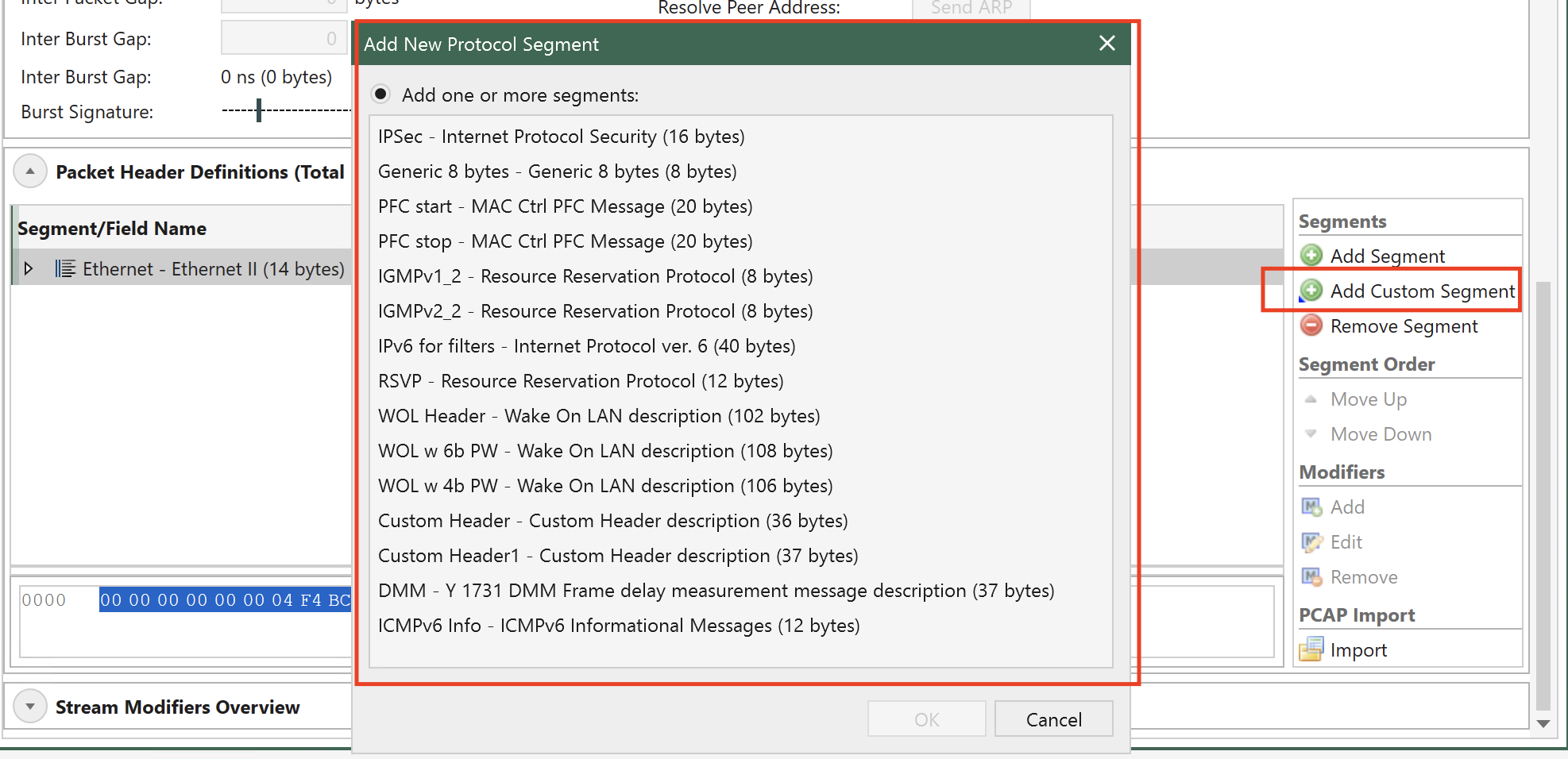
Fig. 5.91 Add Custom Segments
The JSON format of .xdef file:
{
  "Name": "Custom Header",
  "Description": "Custom Header description",
  "SegmentType": 140,               //=> accepted values range: [128 to 191]. It's a unique key, so if more than one file with same SegmentType are detected, it'll load only the first detected one
  "ProtocolFields": [               //=> array of fields for the Custom Segment, you can define as many as you need but always following JSON formatting rules
    {
      "Name": "Custom field 1",
      "BitLength": 8,
      "DisplayType": "Decimal",     //=> accepted values: [Decimal, Binary, Hex, IpV4Address, IpV6Address, MacAddress, DisplayString]
      "DefaultValue": "0"   //=> accepted values can be defined in Decimal or Hex format. Can be separated by commas with no space (,) and each value corresponds to one byte.
    },
    {
      "Name": "Custom field 2",
      "BitLength": 4,
      "DisplayType": "Binary",
      "DefaultValue": "11"  //=> decimal “11” which will be displayed binary in UI as “1011”. Maximum value in this field would be “1111” (4 bits length / “15” decimal)
    },
    {
      "Name": "Custom field 3",
      "BitLength": 2,
      "DisplayType": "Hex",
      "DefaultValue": "0xF"         //=> XenaManager will skip this value and default it to 3 as 0xF is greater than max. possible value for a 2-bit field definition (range 0-3 decimal)
    },
    {
      "Name": "Custom field 4",
      "BitLength": 16,
      "DisplayType": "Hex",
      "DefaultValue": "0xFF, 0xFF"  //=> field defined as 16 bits, so we define 2-byte default values separated by comma and in Hex format, but we can also use Decimal format
    },
    {
      "Name": "Custom field 5",
      "BitLength": 48,
      "DisplayType": "DisplayString",
      "DefaultValue": "0x48,0x65,0x6c,0x6c,0x6f,0x00" //=> field defined as 6 bytes/characters, so to define default value Decimal or Hex format of ASCII values can be used and all 6 bytes needs to be defined
    } ,
    {
      "Name": "MAC Address",
      "BitLength": 48,              //=> MAC address field's length is always 48 / 6 bytes
      "DisplayType": "MacAddress",
      "DefaultValue": "0,0,0,0,0,0"
    },
    {
      "Name": "IPv4 Addr",
      "BitLength": 32,      //=> IPv4 address field's length is always 32 / 4 bytes
      "DisplayType": "IpV4Address",
      "DefaultValue": "0,0,0,0"
    },
    {
      "Name": "IPv6 Addr",
      "BitLength": 128,     //=> IPv6 address field's length is always 128 / 16 bytes
      "DisplayType": "IpV6Address",
      "DefaultValue": "0,0,0,0,0,0,0,0,0,0,0,0,0,0,0,0"
    }
  ]
}
Setting Field Values
You can change any field value by using the associated edit control in the Field Value column. For those fields that have a set of well-known values associated you can also choose one of these values from the dropdown list in the Named Values column.
Finally you may edit the content of the fields directly in the hex editor panel if you are so inclined.
Next-Protocol Type Fields
Certain protocol segment types (such as Ethernet, VLAN and IP) contain fields that indicate the type of the next segment. The segment editor will attempt to set such fields to a correct value when you add, remove or move segments. You can however override the value afterwards if necessary.
Modifiers
Modifiers are specified directly on the field hey are supposed to modify.
Adding Modifier
To add a modifier select the field you want to modify and click the Add button in the Modifiers section in the command panel to the right. You will now be presented with a window allowing you to specify the properties for the modifier. Press the OK button when you are done.
The new modifier will be shown as a child row under the field row. The value in the Field Value column is a read-only string representation of the modifier settings.
Editing Modifier
To edit the properties of an existing modifier select the modifier and click the Edit button in the Modifiers section in the command panel to the right.
Removing Modifier
To remove a modifier select the modifier and click the Remove button in the Modifiers section in the command panel to the right.
Modifier Endianness
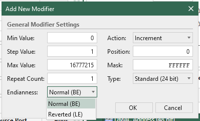
Fig. 5.92 Configure modifier endianness
The endianness of a modifier is specified in the modifier editor. The endianness is used to determine how the modifier value is applied to the field value. The endianness can be set to either Normal (BE) or Reverted (LE).
Normal (BE) means that the modifier inc/dec the field value from the LSB (Least Significant Bit) to the MSB (Most Significant Bit).
Reverted (LE) means that the modifier inc/dec the field value from the MSB to the LSB, as shown in the illustration below.
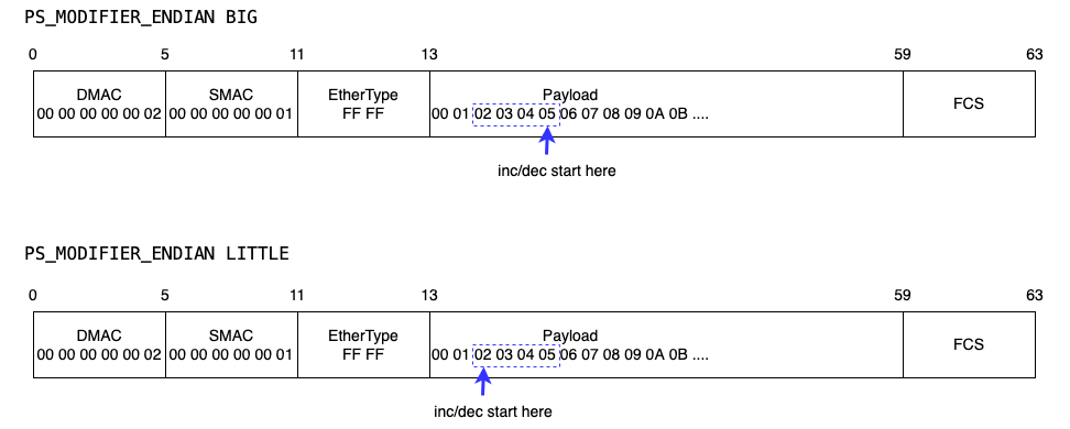
Fig. 5.93 Modifier endianness illustration
Custom Data Field (CDF)
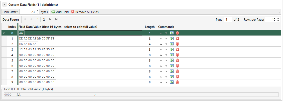
Fig. 5.94 Custom Data Field Editor Overview
Custom Data Field allows you to modify any consecutive bytes in a packet, ranging from one byte to the entire packet. The feature requires that the Payload Mode on the parent port has been set to Custom Data Field. This enables the feature for all streams on this port.
See also
Read more in Freely Programmable Test Packets (Custom Data Fields) for details.
CDF Field Offset
The CDF offset for the stream is the location in the stream data packets where the various CDF data will be placed. All fields for a given stream uses the same offset value. The default value is 0, which means that the CDF data will be placed at the very start of the packet, thus overwriting the packet protocol headers. If you want the CDF data to start immediately after the end of the packet protocol headers you will have to set the CDF field offset manually.
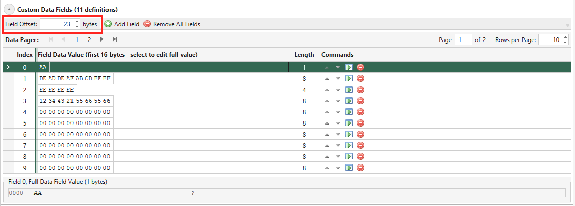
Fig. 5.95 CDF Field Offset
Add/Remove CDF Field
Click the Add Field to start adding a CDF field. Then enter the size of the CDF (by default 8 bytes). This will append a row in the CDF editor table with default values of 00.
You can add more than one CDF fields on a stream. If you have more than one CDF fields on a stream, the stream will generate packet using the CDF fields in a round-robin fashion, which means the first packet uses CDF #0, the second packet uses CDF #1, and so on.
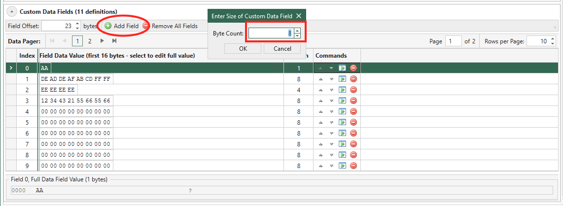
Fig. 5.96 Add CDF Field
Click the Remove button on a CDF to remove it. To remove all CDFs, click the button Remove All Fields.
Fig. 5.97 Remove CDF Field
Edit CDF Field
You can change the CDF index by clicking arrow buttons in Commands as shown above.
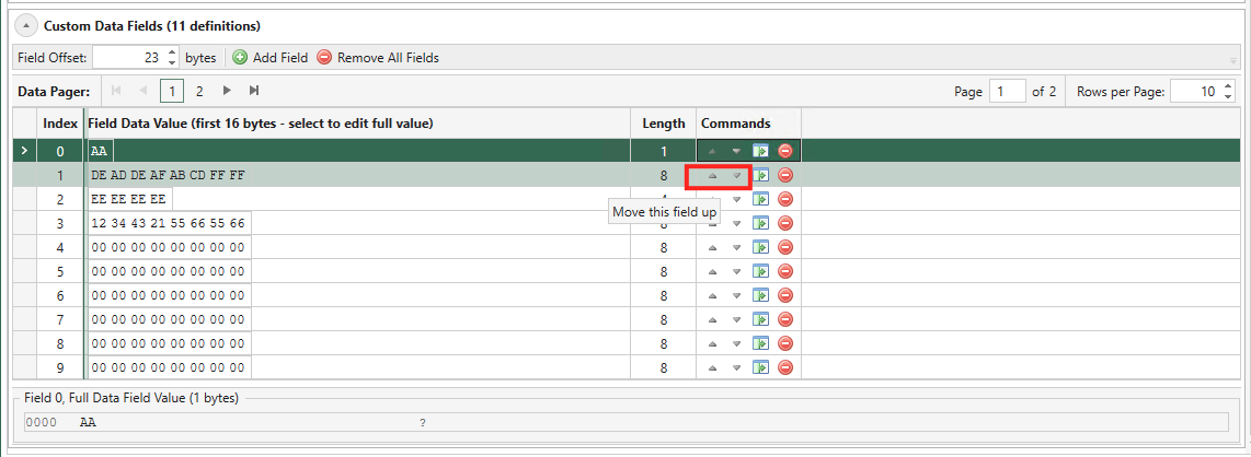
Fig. 5.98 Move CDF Field
You can change the CDF size by clicking third button from the left in Commands as shown above. It is possible to define fields with different data lengths for each stream. If the length of a data field exceeds (packet length - CDF offset) defined for the stream the field data will be truncated when transmitted.
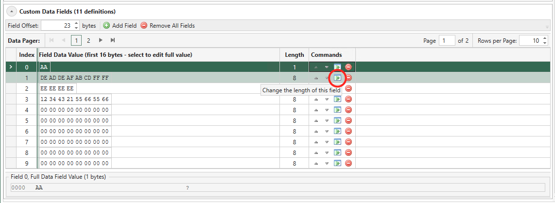
Fig. 5.99 Change Size
To edit the CDF data value, you should use the hex string edit cell.
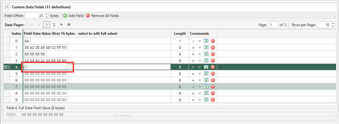
Fig. 5.100 Enter Values
Does My Test Module Support CDF?
In the Port Capabilities part of the Port Properties panel you can see if the test module supports CDFs: If Custom Data Fields Supported is True, the test module supports CDFs (see Fig. 5.101).
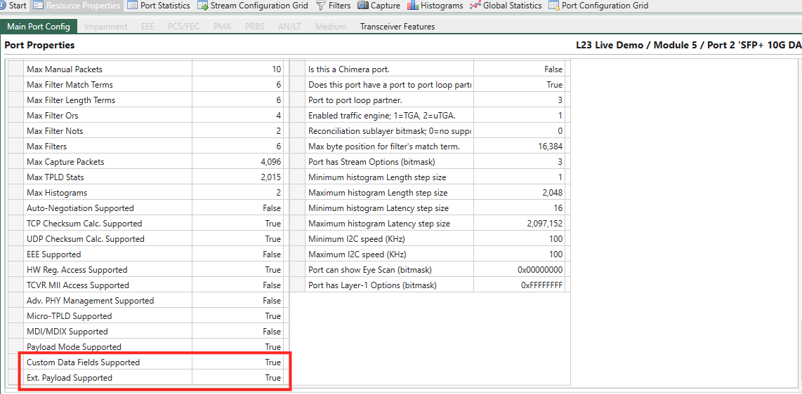
Fig. 5.101 Check if CDF or Ext. Payload is supported
CDF Specifications
The total area available for the CDF function depends on the test module type and port configuration.
Basic CDF specifications per 100G-and-beyond port:
Max number of CDFs: 4096
Max CDF size: Maximum Packet Size for the port.
Max CDF offset = 2032
Max CDF Memory: 262144 bytes (256K bytes)
Note
The Maximum Packet Size for the port is found in the Port Capabilities part of the port properties panel as the Max Packet Length (please observe that different data rates of a port may have different Maximum Packet Size).
When operating the module at lower port speeds, the ports share the above CDF memory and max. number of CDFs per port as follows:
CDF Memory per port = Max 100G-and-beyond CDF Memory / number of ports
Max number of CDFs per port = Max 100G-and-beyond number of CDFs / number of ports
CDF Memory Allocation
The amount of CDF memory used by a single stream is calculated in three steps:
Calculate the CDF size The size of a CDF is a combination of the number of data bytes it contains and its offset into the packet. It is calculated by the following formula:
CDF size = datasize (in bytes) + (offsetbytes_value modulo 8).
For example, a CDF with an offset of 3 and a data size of 234 bytes will have a CDF size of 237 bytes; if the offset is 11, the CDF size is also 237 bytes (11 modulo 8 is 3).
Calculate the CDF block memory size
The CDF memory for each stream is split into blocks, each containing a single CDF. The CDF block sizes are identical for all CDFs on the stream and
2^nbytes long, dimensioned to fit the largest CDF (see step 1). The block sizes can range from 64 bytes to the MTU for the port.As an example: If the largest CDF entry defined for a stream is 237 bytes, the block size will be 256 bytes. Hence, all CDFs for that stream will use 256 bytes of memory, regardless of their individual sizes.
Calculate the CDF memory usage for a single stream
Based on the two steps above, the formula for calculating how much CDF memory a single stream uses is:
Stream CDF memory usage = CDF_memory_block_size * number_of_CDFs
Hence, if the stream described in the example above has 500 CDFs, the total used CDF memory for the stream is: 256 bytes * 500 = 128000 bytes.
Modifiers on CDF
Modifiers cannot be set on CDFs as the feature itself can be viewed as having some of the same characteristics as the modifier option but on a much larger scale.
Tip
You can see CDF as a stream modifier. When multiple CDFs are applied to a stream, the resulting packets appear as if they have an intricate modifier. This modifier varies in both size and values.
Extended Payload
The Extended Payload feature is enabled by selecting Extended Payload in the Payload Mode field of the parent port panel. This enables the feature for all streams on this port. Once the extended payload is enabled, it is possible to set the desired size of the Packet Content area for the stream using the stream’s Extended Payload Editor.
Extended Payload Editor is a powerful UI feature that allows you to customize/configure the entire payload area of a stream in addition to the predefined payload pattern e.g. Incrementing 8-bits, Pattern, Random, and PRBS-31.
Please note that the Extended Payload Editor is only enabled when you set the port’s Payload Mode to Extended Payload as shown in Fig. 5.102. This will enable all the streams under the port to accept the extended payload configuration.
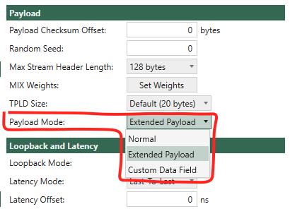
Fig. 5.102 Set port’s payload mode to Extended Payload to enable the feature.
You can find the Extended Payload Editor as shown in Fig. 5.103 on the stream once the parent port has Payload Mode to Extended Payload. Click Open Editor and paste the payload data in hex strings and click OK. Then you can see your payload data in a byte-ascii grid view where each row contains 16 bytes.
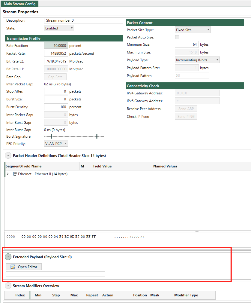
Fig. 5.103 Open Extended Payload editor
If you want to do adjustment on some bytes, you can click on the byte and enter the value as shown in Fig. 5.104.
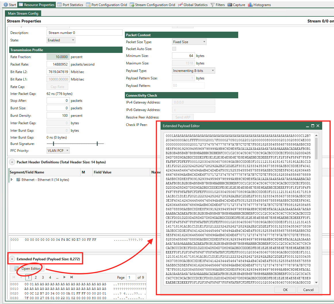
Fig. 5.104 Adjust some byte values
If the Extended Payload is not empty, the stream will use the provided payload data. If empty, the stream will use the configuration from .
To quickly import the payload data from a pcap file, you can use Wireshark to copy the payload data , as shown in Fig. 5.105, and then paste it into the Extended Payload Editor.
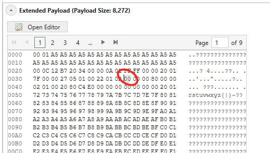
Fig. 5.105 Copy packet payload from pcap
Note
Please note that the total test packet size must be minimum the size of the stream protocol headers + extended payload + TPLD + FCS.
If the total packet size is shorter than that, the Extended Payload is cut to fit the test packet.
If it is longer, padding will be inserted between the Extended Payload and the TPLD.
Like a CDF, the Extended Payload is fit into a block, which is 2^n bytes long. The block sizes can range from 64 bytes to MTU for the port; the smallest size where the Extended Payload fits in is used. Bytes in the block that is not used by the Extended Payload is filled with padding like CDF blocks.
Fig. 5.106 illustrates a test packet with 120 bytes Extended Payload in a 166 byte test packet. For the test packet in Fig. 5.106 this means that there is room for the Extended Payload plus the remaining 8 bytes in the memory block that the Extended Payload occupies.
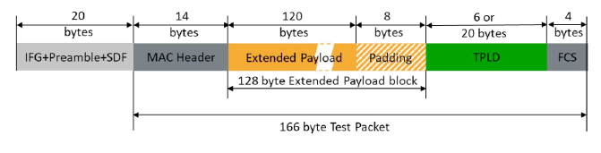
Fig. 5.106 Test packet with 120 bytes Extended Payload
See also
Read more in Freely Programmable Test Packets (Custom Data Fields) for details.
Does My Test Module Support Extended Payload?
In the Port Capabilities part of the Port Properties panel you can see if the test module supports CDFs: If Ext. Payload Supported is True, the test module supports Extended Payload (see Fig. 5.101).
Extended Payload Memory Allocation
The Extended Payload feature is a special application of the CDF feature with an offset matching the headers in the test package. Therefore, the sections on CDF specifications and CDF Memory Allocation also apply for the Extended Payload feature
Modifiers on Extended Payload
It is possible to set a modifier in the Extended Payload area just as it is for a normal protocol field.
Tip
It is different from CDF because Extended Payload is fundamentally a more advanced payload compared to the basic.
Test Payload
Test Payload (Normal)
Each Xena test packet contains a special proprietary data area called the Test Payload Data (TPLD), which contains various information about the packet and is identified by a Test Payload ID (TID). The TPLD is located just before the Ethernet FCS and consists of the following sections:
Field |
Length |
Explanation |
|---|---|---|
Payload Integrity Checksum (optional) |
2 bytes |
See the note. |
Sequence Number |
3 bytes |
Packet sequence number used for loss and misordering detection. |
Timestamp |
4 bytes |
Timestamp value used for latency measurements. |
Test Payload ID (TID) |
2 bytes |
Test payload identifier used to identify the sending stream. |
Payload Integrity Offset |
1 byte |
Offset in packet from where to calculate payload integrity. |
First Packet Flag |
1 bit |
Set if this is the first packet after traffic is started. |
Checksum Enabled |
1 bit |
Set if payload integrity checksum is used. |
<reserved> |
7 bits |
|
Payload Integrity Offset (MSB) |
3 bits |
Offset in packet from where to calculate payload integrity, MSB (bits 10:9:8) |
Timestamp Decimals |
4 bits |
Additional decimals for the timestamp. |
Checksum |
8 bytes |
TPLD integrity checksum (CRC-32) |
Total TPLD Size |
20 or 22 bytes |
Note
If the Payload Checksum Offset is enabled on the parent port (value > 0) , then an additional 2-byte checksum field is inserted in the beginning of the TPLD, just before the Sequence Number. This increases the total size of the TPLD to 22 bytes.
Test Payload (Micro)
Field |
Length |
Explanation |
|---|---|---|
First Packet Flag |
1 bit |
Packet sequence number used for loss and misordering detection. |
<reserved> |
1 bit |
|
Test Payload ID (TID) |
10 bits |
Test payload identifier used to identify the sending stream. |
Timestamp |
28 bits |
Timestamp value used for latency measurements. |
Checksum |
8 bits |
TPLD integrity checksum (CRC-32) |
Total Micro-TPLD Size |
6 bytes |
The selection between the default TPLD and the micro-TPLD is done on the parent port. It is thus not possible to use different TPLD types for streams on the same port.
Timestamp Calculation
Timestamp consists of two parts: <Timestamp> and <Timestamp Decimals> (<Timestamp Decimals> not available in micro TPLD).
Timestamp is calculated into nanoseconds by the equation below:
Timestamp = <Timestamp>*8 + <Timestamp Decimals>/2
For instance:

if <Timestamp> = 0x7a2ce291, and <Timestamp Decimals> = 0x0d,
then Timestamp = 2049761937*8 + 13/2 = 16,398,095,502 nsec
Disabling Test Payload
The Test Payload can also be completely disabled for any given stream by setting the Test Payload ID (TID) value for the stream to the value -1.
Xena Wireshark Plugin for TPLD
You can download the Xena TPLD Wireshark pluggin from xenanetworks/tpld-parser-wireshark
Xena offers a Wireshark integration via a dedicated LUA plugin. It allows users to easily read the information in the Xena test signature field. The plugin supports Wireshark 3.x and above.