Time and Clock Configuration
Timing Configuration
Property |
Explanation |
|---|---|
Timing Source |
Control how the test module time-stamp clock is running, either freely in the chassis, on the module itself or locked to external system time (requires the TimeSynch option). Running with free chassis ore module time allows nano-second precision measurements of latencies, but only when the transmitting and receiving ports are in the same chassis or on the same module. Running with locked external time enables inter-chassis latency measurements, but can introduce small time-discontinuities as the test module time is adjusted. |
Local Clock Adjustment |
Makes a small adjustment to the local clock of the test module, which drives the TX rate of the test ports. The property value is the desired adjustment from the nominal value, in parts-per-billion, positive or negative. |
SMA Output Function |
For test modules with SMA connectors, this property selects the function of the SMA output. |
SMA Input Function |
For test modules with SMA connectors, this property selects the function of the SMA input. |
TX Clock Source |
For test modules with advanced timing features, this property selects what drives the port TX rates. |
TX and SMA Clock Filter |
For test modules with advanced timing features, this property determines the loop bandwidth on the TX clock filter. |
Clock Sweep
Note
Clock sweep function is not available across all modules.
Clock offset sweep provides the ability to let the system make controlled clock variations on all ports on a module. The function works together with the Timing configuration function.
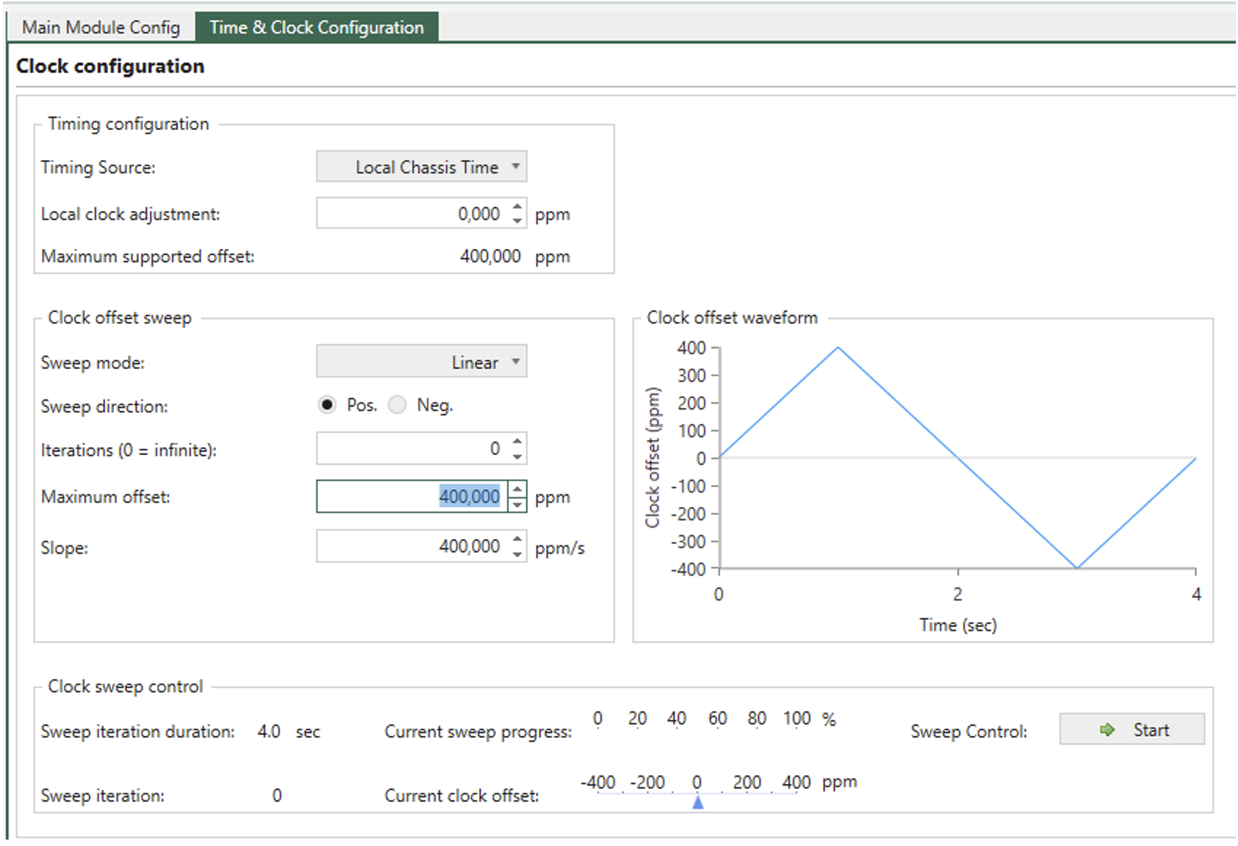
Fig. 5.5 Clock sweep
Clock Offset Sweep
Sweep will be done as a symmetrical increase and decrease in ppm starting from the configured Local clock Adjustment
Property |
Explanation |
|---|---|
Sweep mode |
Determines if the sweep is done as a Linear or Step sweep. Step size and duration is calculated based on maximum offset and sweep iteration duration. |
Sweep direction |
Determines if the sweep should start with an increase or decrease in ppm |
Iterations |
Determines if the system performs a fixed number of iterations before stopping, or infinite iterations. Setting the parameter to 0, will make infinite sweeps until stopped by the user |
Maximum Offset |
Determines the maximum ppm offset value possible. The value can be configured until ppm offset reaches the limit of Maximum supported offset deducted the numerical value of the Local clock adjustment. |
Slope |
Configures ppm/s. Adjusting slope will affect the sweep iteration duration. |
Note
Max Sweep duration is 64 secs. It is not possible to start sweep unless Max Sweep duration is 64 sec or less
Clock Offset Waveform
Clock offset waveform shown in Fig. 5.5 illustrates the configured sweep configuration with the parameters listed above.
Clock Sweep Control
Property |
Explanation |
|---|---|
Sweep iteration duration |
Shows the duration (in seconds) of an iteration for the configured ppm sweep |
Sweep iteration |
Shows the number of iterations done of the configured ppm sweep |
Current sweep progress |
Shows the progress (in %) of the current iteration for the configured ppm sweep |
Current clock offset |
Indicates the value of the current clock offset (in ppm). |
Sweep control |
Start and stop ppm sweep Note PPM sweep can be done both with and without active traffic on the ports on the module. |