6.6.3. Extended Mode
Extended filtering mode allows the user to filter on any pattern within the first 128 bytes of the packet.
The filtering is done by specifying a filter value of 128 bytes and filter mask of 128 bytes.
The extended filter is illustrated in Fig. 6.29.
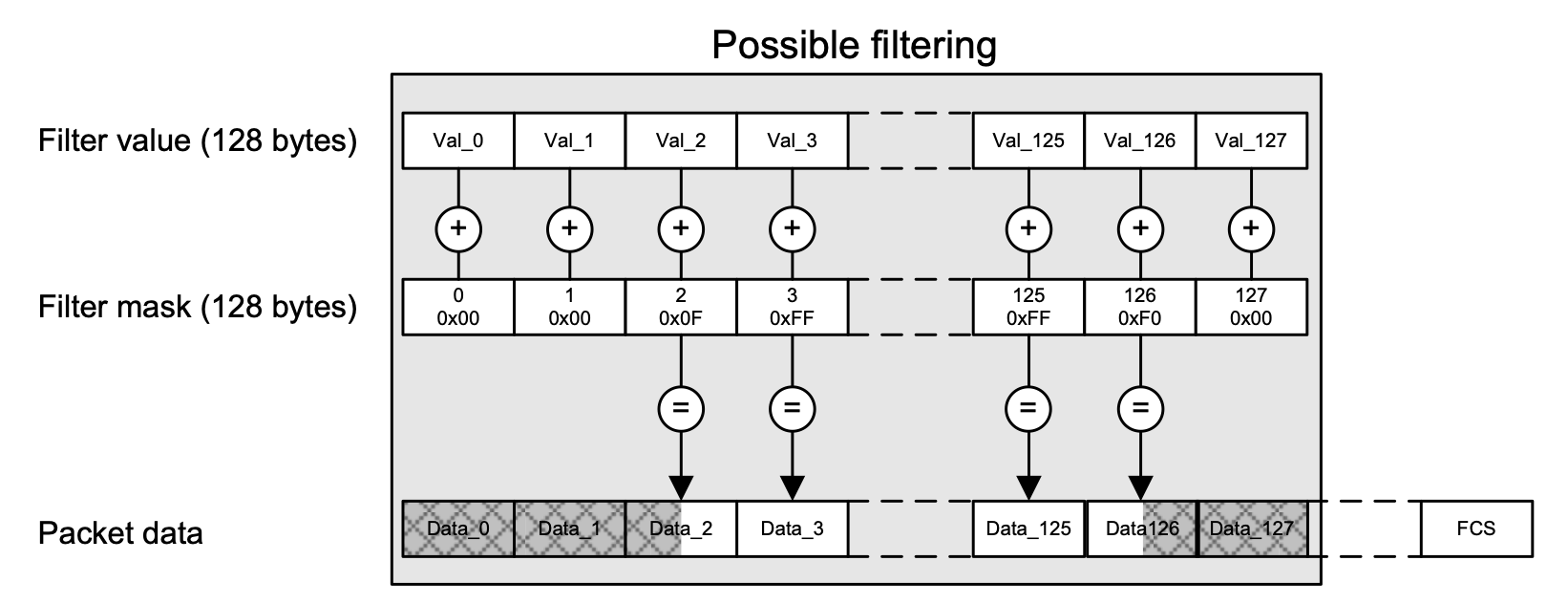
Fig. 6.29 Extended Filtering mode.
Fig. 6.29 illustrates that if the filter mask of a given byte is non-zero (bytes 2, 3, 125 and 126), the corresponding filter value byte is matched against the corresponding byte in the incoming packet at the bit positions indicated by a 1 in the mask bit.
If the mask byte is zero (bytes 0, 1, 127), the corresponding byte in the incoming packet is ignored in the flow filter.
If an incoming packet is shorter that the specified filter, it will not match.
UI Configuration
To configure a flow filter using extended filtering, select the relevant flow and go to the tab and select Extended mode, which will bring up the UI interface illustrated in Fig. 6.30.
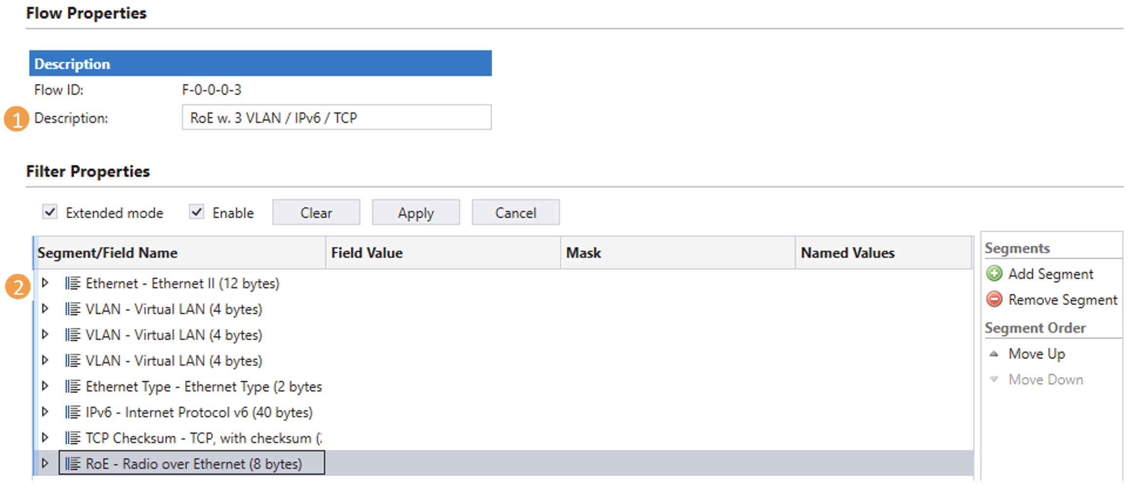
Fig. 6.30 Extended filtering.
At the top it is possible to assign a descriptive text to the flow (#1), which is used to identify the flow in the statistics tabs.
The protocol segment list illustrated in Fig. 6.30 (#2) can be manipulated using the Add Segment and Remove Segment buttons.
To add a protocol layer use the Add Segment button and select relevant protocols from the predefined protocol list illustrated in Fig. 6.31.
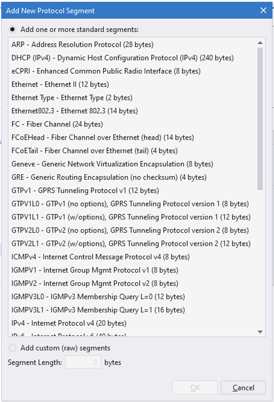
Fig. 6.31 Extended filtering protocols.
To add custom protocol segments use Add custom (raw) segments at the bottom of Fig. 6.31, by simply supplying the length of the segment in bytes.
Note
Notice that the total sum of the protocols can not exceed 128 bytes.
For each of the selected protocols, it is configurable which bits in the packet to match and which values to match against. An example of how to configure the IPv6 encapsulation is illustrated in Fig. 6.32.
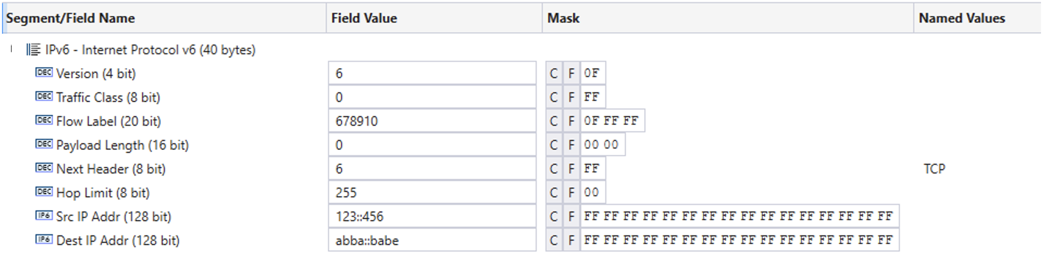
Fig. 6.32 Pv6 filter configuration.
Once the filter is complete, be sure to click Enable and press the Apply button, illustrated in Fig. 6.30.
For info on how to configure extended filtering using scripting, see Section Scripting.
Scripting
The bytes in the filter value and filter mask are structured as a list of protocols. Each protocol requires a certain number of bytes to be specified in the filter value and filter mask. Each protocol in the protocol list is identified using a protocol index, reflecting the number of the protocol in the list. The first protocol will be assigned protocol index = 1.
Fig. 6.33 illustrates an example of a protocol list including the protocols names, protocol indices (in parenthesis) and the length of each protocol in bytes.
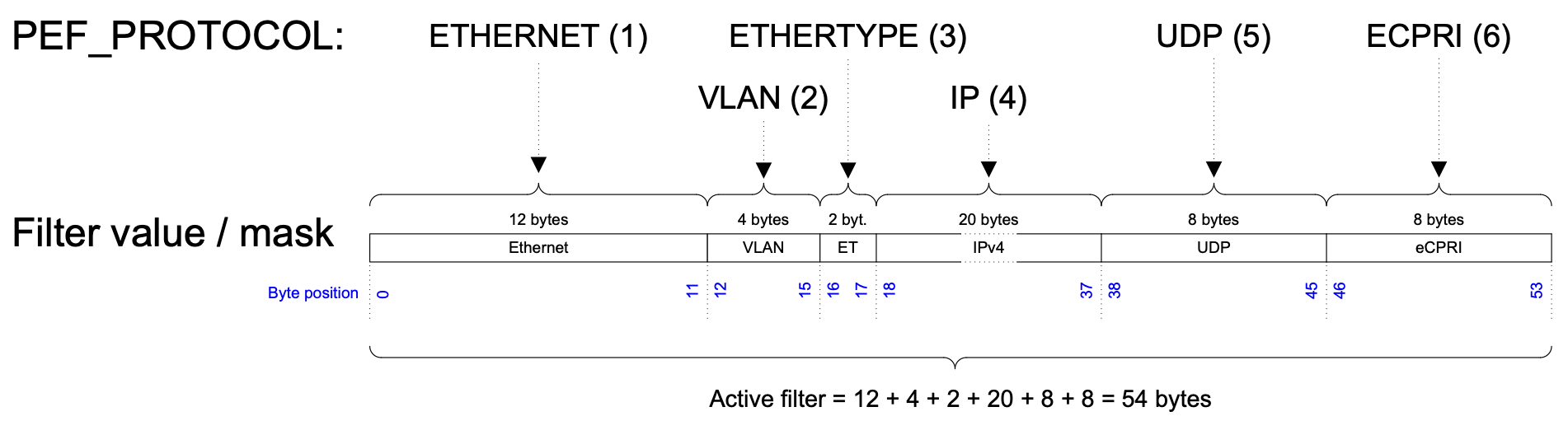
Fig. 6.33 Flow filter protocol specification.
The protocol list shown here contains the protocols listed in Table 6.10.
Protocol |
Protocol index |
Length (bytes) |
|---|---|---|
ETHERNET |
1 |
12 |
VLAN |
2 |
4 |
ETHERTYPE |
3 |
2 |
IPv4 |
4 |
20 |
UDP |
5 |
8 |
eCPRI |
6 |
8 |
The filter protocol list is specified using the script command PEF_PROTOCOL and takes as argument all the protocols to be included in the current filter. Notice, that the protocol list must include ETHERNET at protocol index = 1, to indicate that the incoming packets are Ethernet packets. In addition to the predefined protocols, it is possible to define custom protocols.
Note
The example below illustrates how to select extended filtering mode and configure the protocol list illustrated in Fig. 6.33.
PEF_MODE    [fid,0] EXTENDED
PEF_PROTOCOL[fid,0] ETHERNET VLAN ETHERTYPE IP UDP ECPRI
PEF_APPLY   [fid]
The combined length of the protocols configured using PEF_PROTOCOL defines the length of the active filter in bytes. Referring to the example from Fig. 6.33, this amounts to 54 active filter bytes. This implies that the first 54 bytes of the filter value and the filter mask must be configured. The remaining filter mask bytes will automatically be set to zero.
Note
Notice that the active filter can never be configured to be more than 128 bytes.
Once the protocol list has been defined, the protocol index implicitly assigned to every protocol, can be used to set the protocol filter value and protocol filter mask, using PEF_VALUE and PEF_MASK respectively.
Using the protocol index as input to PEF_VALUE and PEF_MASK only the value of that protocol is modified. The protocol value must reflect the byte values in the protocol being referenced. Figure 34 illustrates the configuration of the 8 bytes in the UDP protocol.

Fig. 6.34 Configuring UDP protocol segment.
Note
The example below illustrates how to configure the UDP (protocol index = 5) protocol filtering from the example in Fig. 6.33 with UDP source Port = 0x1122 and UDP length = 0x3344, while UDP destination port and UDP checksum are ignored.
PEF_VALUE[fid,0,5] 0x1122000033440000
PEF_MASK [fid,0,5] 0xFFFF0000FFFF0000
PEF_APPLY[fid]
Protocol index 0 has a special significance. It is used to work on the entire active filter value and filter mask as a single array of bytes.
Once the protocol list has been defined, you can use index 0 to define the entire filter value / mask or use the individual protocol indices to configure the protocols individually. I.e. using protocol index 0 for the example in Fig. 6.33 will modify all 54 bytes of the active filter value / mask.