6.6.2. Basic Mode
In Basic mode, the flow filters are composed of multiple sub-filters, which match against different protocol layers. Sub-filters are named after the protocol layer at which they are applied.
The configuration options available in basic mode are illustrated in Fig. 6.18.
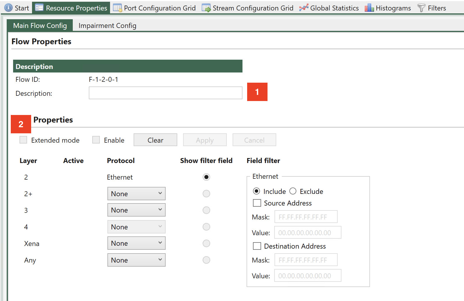
Fig. 6.18 Flow sub-filters.
Fig. 6.18 illustrates that it is possible to enter a flow description, which will be used in the UI to identify statistics
To enter basic mode you must de-select Extended mode (See Fig. 6.18).
Note
Corresponding CLI command: PEF_MODE [fid,0] BASIC and PEF_APPLY[fid,0]
In Basic mode, the sub-filters are used to define the encapsulation of packets, even when they are not used for filtering. E.g. defining 1 VLAN at sub-filter 2+ (as illustrated in :numref:`` 18) specifies that packets must have 1 VLAN, even when no fields in the VLAN are used for matching.
Flow filters can be defined on a port without enabling impairments. Simply configure the desired flow sub-filters, click Enable and then Apply. If this is done, flow statistics will be updated, but no impairments are active.
To activate impairments at the flow level, the impairments must first be enabled at the port level (see Figure 38). If impairments are not enabled at the port level, all flow impairments are inactive.
All sub-filters allow specifying whether packets that match the corresponding sub-filter will be mapped to the flow (Include option)or whether packets that do not match the sub-filter are mapped to the flow (Exclude option).
Basic mode implements the shadow and working registers.
Ethernet Sub-Filter
A sub-filter can be applied at the Ethernet layer. The filter includes the following fields:
Ethernet Destination MAC address (DMAC).
Ethernet Source MAC address (SMAC).
The UI Ethernet sub-filter options are illustrated in Fig. 6.19.
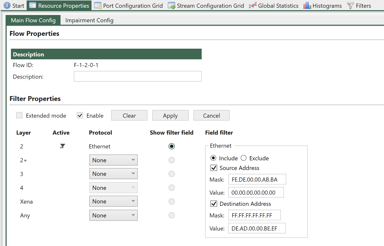
Fig. 6.19 Ethernet sub-filter.
To match against SMAC or DMAC, check the boxes Source Address or Destination Address respectively.
If none of these checkboxes are checked, the sub-filter will not be used for matching. However, the remaining sub-filters will always assume that packets are Ethernet packets, including DMAC, SMAC and Ethertype.
When matching against DMAC / SMAC, a 48 bit mask is configured to identify which bits in the MAC address are used for matching. Filtering bits configured = 1 will be used for matching.
Note
The example below illustrates how to filter for packets with DMAC = 0xFEDE0000ABBA and SMAC = 0xDEAD0000BEEF (all bits used for matching).
PEF_ETHSETTINGS[fid,0] AND INCLUDE
PEF_ETHSRCADDR [fid,0] ON 0xFEDE0000ABBA 0xffffffffffff
PEF_ETHDESTADDR[fid,0] ON 0xDEAD0000BEEF 0xffffffffffff
PEF_ENABLE     [fid,0] ON
PEF_APPLY      [fid]
Layer 2+ Sub-Filter
The Layer 2+ sub-filter allows the user to specify 1 VLAN, 2 VLANs or an MPLS label after the Ethernet header.
Single VLAN Tag
This sub-filter allows filtering based on a single VLAN tag. The filter includes the following fields:
VLAN ID (VID)
VLAN PCP bits
Selecting 1 VLAN Tag causes the flow filter to verify that the TPID is 0x8100, in addition to any VID / PCP matching configured.
The available UI configuration options for 1 VLAN Tag are illustrated in Fig. 6.20.
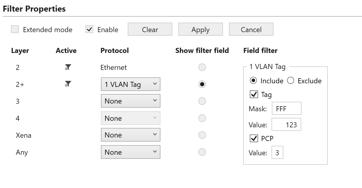
Fig. 6.20 Layer 2+ sub-filter (1 VLAN)
To match against the VID, check the Tag checkbox and to match against the PCP bits, check the PCP checkbox.
The VID matching includes a mask to indicate that only selected bits (mask bit = 1) are used for matching. The PCP value is always matched against all 3 PCP bits in the UI.
If none of the checkboxes Tag or PCP are checked, no filtering is done on the VID / PCP values, but selecting the 1 VLAN Tag option will indicate that packets mapped to this flow by higher layer sub-filters must have a single VLAN present. This includes checking TPID = 0x8100.
Note
The example below illustrates how to filter packets with VID = 1234 and PCP = 3 (all bits used for matching).
PEF_L2PUSE       [fid,0]             VLAN1 (1)
PEF_VLANSETTINGS [fid, 0]            AND (1) INCLUDE (1)
PEF_VLANTAG      [fid, 0, VLAN1 (0)] ON (1)  1234 0xFFF
PEF_VLANPCP      [fid, 0, VLAN1 (0)] ON (1)  3    0x7
PEF_ENABLE       [fid,0]             ON
PEF_APPLY        [fid]
Double VLAN Tags
This sub-filter allows filtering based on a 2 VLAN Tags. The filter includes the following fields:
Inner VLAN VID.
Inner VLAN PCP bits.
Outer VLAN VID.
Outer VLAN PCP bits.
Selecting 2 VLAN Tags causes the flow filter to verify that the TPID of the inner VLAN is 0x8100 and the TPID of the outer VLAN is 0x88A8, in addition to any VID / PCP checking configured.
The available UI configuration options for 2 VLAN Tags are illustrated in Fig. 6.21.
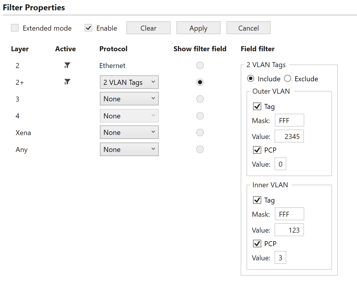
Fig. 6.21 Layer 2+ sub-filter (2 VLANs)
To match against the inner and / or outer VID, check the corresponding Tag checkbox and to match against the inner and / or outer PCP bits, check the corresponding PCP checkbox.
The VID matching includes a mask to indicate that only selected bits (mask bit = 1) are used for matching. The PCP value is always matched against all 3 PCP bits in the UI.
If none of the checkboxes Tag or PCP are checked, no filtering is done on the VID / PCP values, but selecting the 2 VLAN Tags option will indicate that packets mapped to this flow by higher layer sub-filters must have two VLANs tags present. This includes the TPID matching described above.
Note
The example below illustrates how to filter for packets with outer VID = 2345, outer PCP = 0, inner VID = 1234 and inner PCP = 3 (all bits used for matching).
PEF_L2PUSE       [fid,0]             VLAN2 (2)
PEF_VLANSETTINGS [fid, 0]            AND (1) INCLUDE (1)
PEF_VLANTAG      [fid, 0, VLAN2 (1)] ON (1)  2345 0xFFF
PEF_VLANPCP      [fid, 0, VLAN2 (1)] ON (1)  0    0x7
PEF_VLANTAG      [fid, 0, VLAN1 (0)] ON (1)  1234 0xFFF
PEF_VLANPCP      [fid, 0, VLAN1 (0)] ON (1)  3    0x7
PEF_ENABLE       [fid,0]             ON
PEF_APPLY        [fid]
MPLS
This sub-filter allows filtering based on a MPLS label. The filter includes the following fields:
MPLS label.
MPLS traffic class (TC) bits.
The available UI configuration options for MPLS are illustrated in Fig. 6.22.
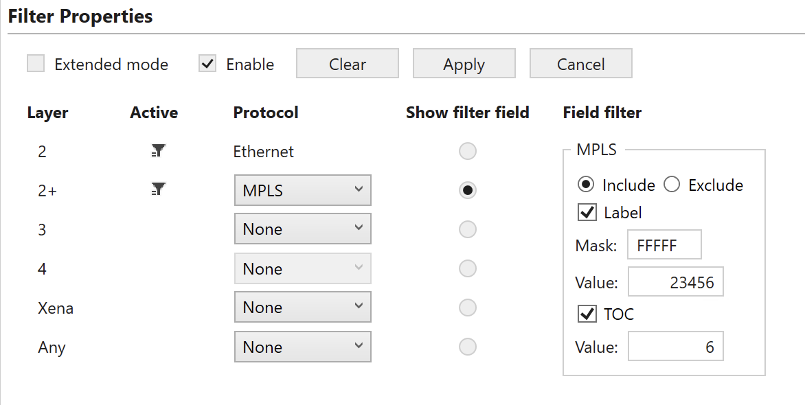
Fig. 6.22 Layer 2+ sub-filter (MPLS)
To match against the MPLS label, check the corresponding Label checkbox and to match against the Traffic Class (TC) bits, check the TOC checkbox. The label matching includes a mask to indicate that only selected bits (mask bit = 1) are used for matching. The TC value is always matched against all 3 TC bits in the UI.
If none of the checkboxes Label or Exp/ToC are checked, no filtering is done on the label / TC values, but selecting the MPLS option will indicate that packets mapped to this flow by higher layer sub-filters must have a MPLS label (32 bits) present.
Note
The example below illustrates how to filter for packets with label = 23456 and TC = 6 (all bits used for matching).
PEF_L2PUSE       [fid,0] MPLS (3)
PEF_MPLSSETTINGS [fid,0] AND (1) INCLUDE (1)
PEF_MPLSLABEL    [fid,0] ON (1) 23456 0xFFFFF
PEF_MPLSTOC      [fid,0] ON (1) 6 0x07
PEF_ENABLE       [fid,0] ON
PEF_APPLY        [fid]
Layer 3 Sub-Filter
The Layer 3 sub-filter allows the user to specify an IPv4 or an IPv6 header after the Ethernet header described in Section Ethernet Sub-Filter and the layer 2+ encapsulation described in Section Layer 2+ Sub-Filter.
There is no explicit selection between the IPv4 and the IPv6 filtering in the script commands, but if both are configured, only the later will be active.
IPv4
This sub-filter allows filtering based on the following IPv4 fields:
The available UI configuration options for IPv4 are illustrated in Fig. 6.23.
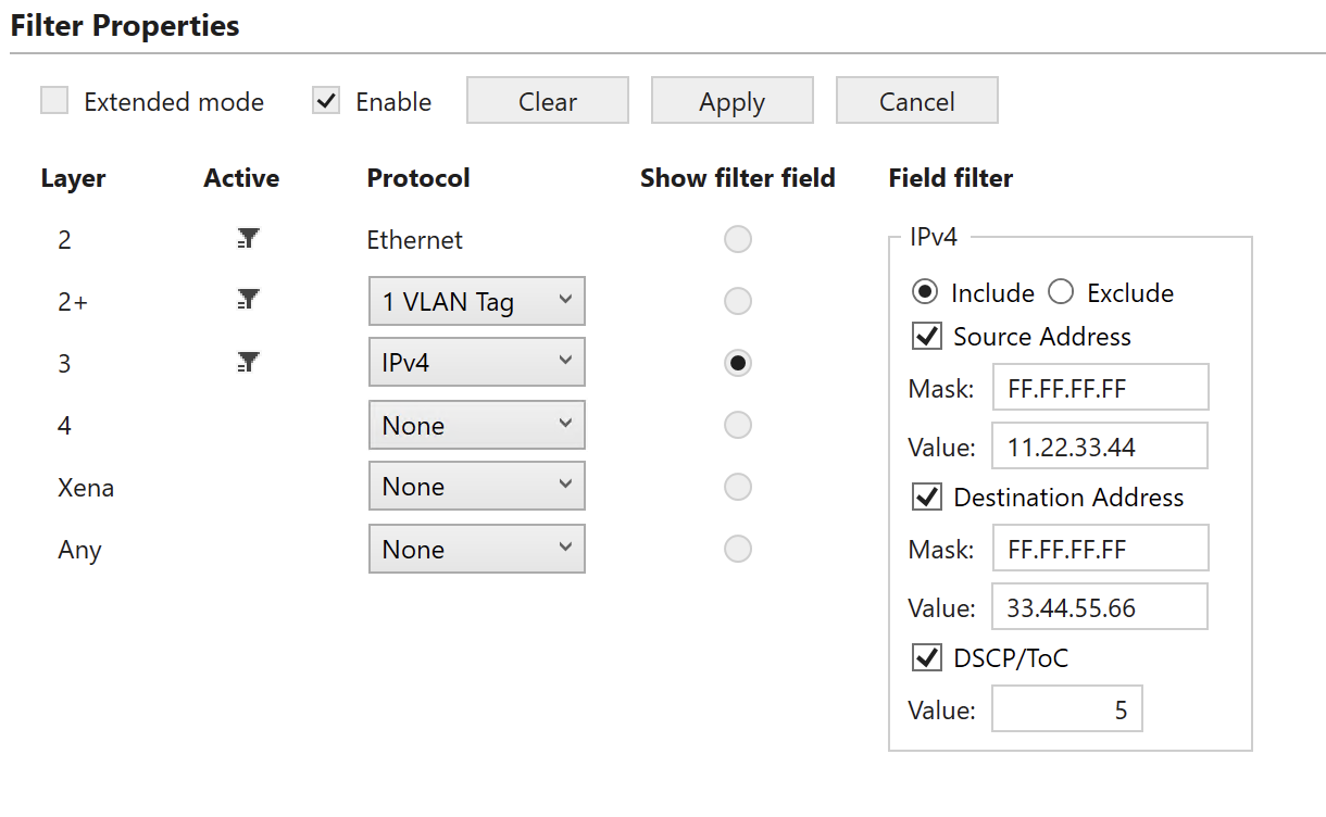
Fig. 6.23 Layer 3 sub-filter (IPv4)
To match against IPv4 SIP, DIP or DSCP/ToC, check the corresponding checkboxes.
The DIP and SIP matching includes a mask to indicate that only selected bits (mask bit = 1) are used for matching. The DSCP value is always matched against all 6 bits in the UI.
If none of the checkboxes SIP, DIP or DSCP/ToC are checked, no filtering is done at the IPv4 layer, but selecting the IPv4 option will indicate that packets mapped to this flow by higher layer sub-filters must have a IPv4 header present.
Note
The example below illustrates how to filter for packets with SIP = 11.22.33.44, DIP = 33.44.55.66 and DSCP = 5 (all bits used for matching).
PEF_L3USE        [fid,0] IP4 (1)
PEF_IPV4SETTINGS [fid,0] ON (1) INCLUDE (1)
PEF_IPV4SRCADDR  [fid,0] ON (1) 11.22.33.44 0xFFFFFFFF
PEF_IPV4DESTADDR [fid,0] ON (1) 33.44.55.66 0xFFFFFFFF
PEF_IPV4DSCP     [fid,0] ON (1) 0x14 0xFC
PEF_ENABLE       [fid,0] ON
PEF_APPLY        [fid]
IPv6
This sub-filter allows filtering based on the following IPv6 fields:
Destination IP address (DIP)
Source IP address (SIP)
IPv6 DSCP
The available UI configuration options for IPv6 are illustrated in Fig. 6.24.
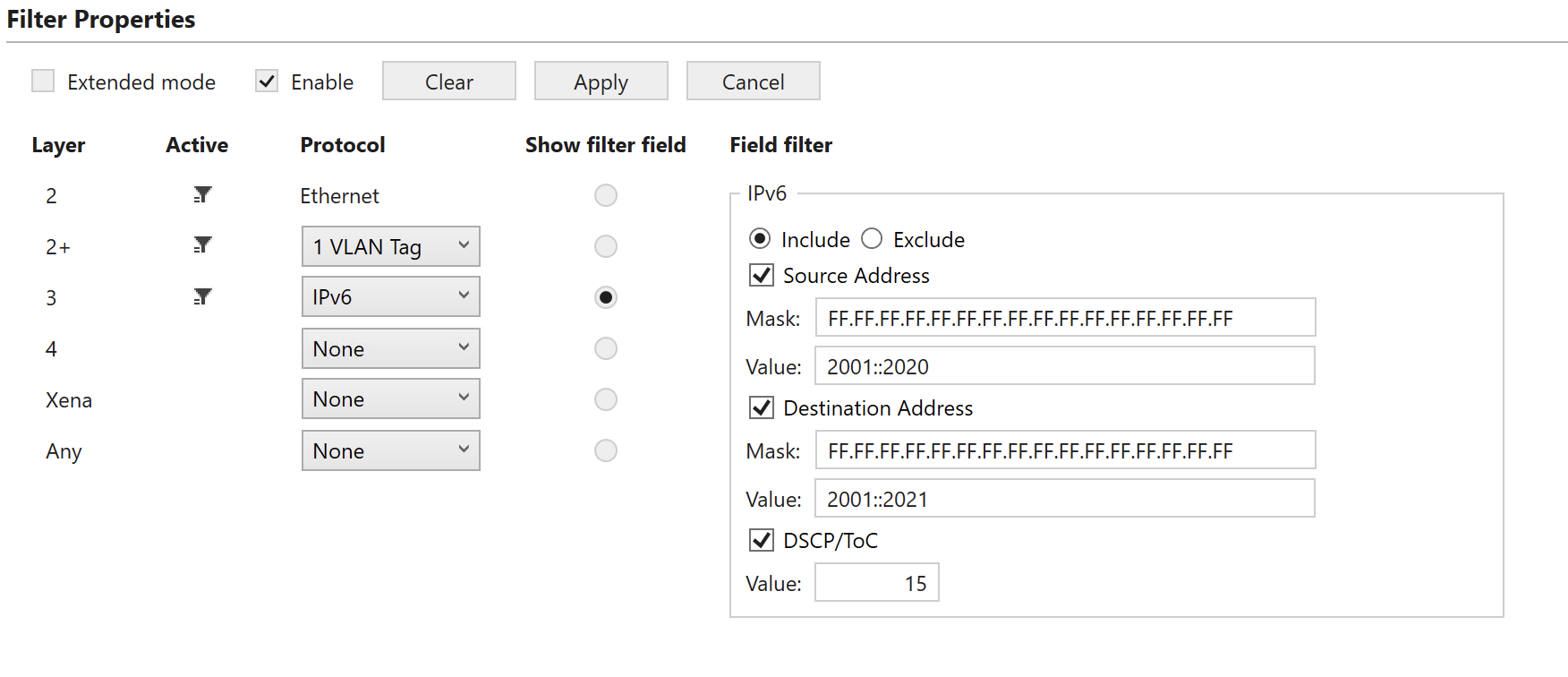
Fig. 6.24 Layer 3 sub-filter (IPv6)
To match against IPv6 SIP, DIP or DSCP/ToC, check the corresponding checkboxes.
The DIP and SIP matching includes a mask to indicate that only selected bits (mask bit = 1) are used for matching. The DSCP value is always matched against all 6 bits in the UI.
If none of the checkboxes SIP, DIP or DSCP are checked, no filtering is done at the IPv6 layer, but selecting the IPv6 option will indicate that packets mapped to this flow by higher layer sub-filters must have a IPv6 header present.
Note
The example below illustrates how to filter for packets with SIP = 2001:123:4455::6677:89A:BBCC, DIP = 2020:a98:8877::6655:432:1100 and DSCP = 15 (all bits used for matching).
PEF_L3USE        [fid,0] IP6 (2)
PEF_IPV6SETTINGS [fid,0] ON (1) INCLUDE (1)
PEF_IPV6SRCADDR  [fid,0] ON (1)  0x200101234455000000006677089ABBCC 0xFFFFFFFFFFFFFFFFFFFFFFFFFFFFFFFF
PEF_IPV6DESTADDR [fid,0] ON (1) 0x20200a98887700000000665504321100 0xFFFFFFFFFFFFFFFFFFFFFFFFFFFFFFFF
PEF_IPV6TC       [fid,0] ON (1) 0x3C 0xFC
PEF_ENABLE       [fid,0] ON
PEF_APPLY        [fid]
Layer 4 Sub-Filter
The Layer 4 sub-filter allows the user to specify a UDP or a TCP header after the Ethernet header described in Section Ethernet Sub-Filter, the layer 2+ encapsulation described in Section Layer 2+ Sub-Filter and layer 3 sub-filtering described in Section Layer 3 Sub-Filter.
Note
Notice that the UDP / TCP port configuration is only available if a IPv4/IPv6 header was configured at layer 3.
There is no explicit selection between the UDP port and the TCP port filtering in the script commands, but if both are configured, only the later will be active.
TCP
This sub-filter allows filtering based on the following TCP fields:
TCP source port.
TCP destination port.
The available UI configuration options for TCP filtering are illustrated in Fig. 6.25.
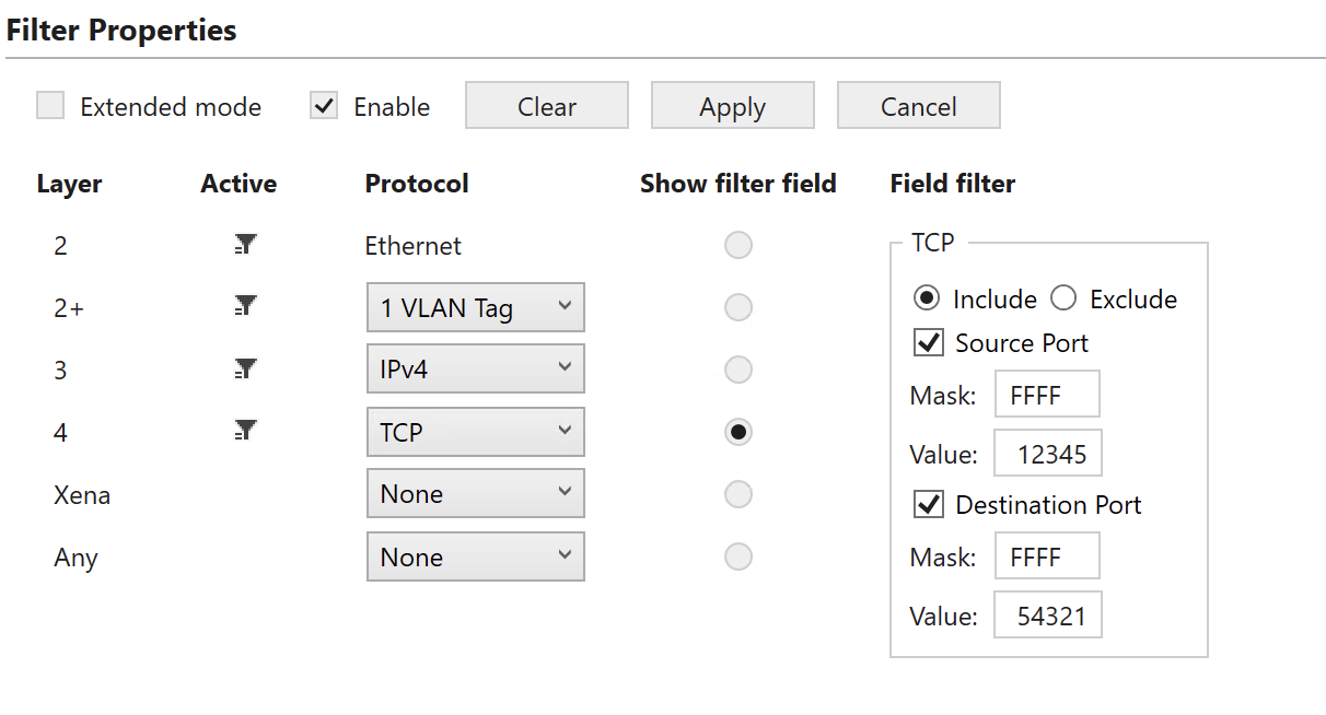
Fig. 6.25 Layer 4 sub-filter (TCP).
To match against the TCP source port or the destination port, check the corresponding checkboxes.
Both the TCP source port and destination port matching includes a mask to indicate that only selected bits (mask bit = 1) are used for matching. If none of the checkboxes Source Port or Destination Port are checked, no filtering is done at the TCP layer, but selecting the TCP option will indicate that packets mapped to this flow by other sub-filters must have a TCP header present.
Note
The example below illustrates how to filter for packets with TCP source port = 12345 and destination port = 54321 (all bits used for matching).
PEF_TCPSETTINGS [fid,0] ON (1) INCLUDE (1)
PEF_TCPSRCPORT  [fid,0] ON (1) 12345 0xFFFF
PEF_TCPDESTPORT [fid,0] ON (1) 54321 0xFFFF
PEF_ENABLE      [fid,0] ON (1)
PEF_APPLY       [fid]
UDP
This sub-filter allows filtering based on the following UDP fields:
UDP source port.
UDP destination port.
The available UI configuration options for UDP filtering are illustrated in Fig. 6.26.
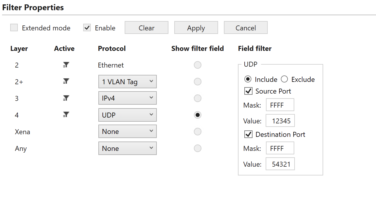
Fig. 6.26 Layer 4 sub-filter (UDP)
To match against the UDP source port or the destination port, check the corresponding checkboxes.
Both the UDP source port and destination port matching include a mask to indicate that only selected bits (mask bit = 1) are used for matching. If none of the checkboxes Source Port or Destination Port are checked, no filtering is done at the UDP layer, but selecting the UDP option will indicate that packets mapped to this flow by higher layer sub-filters must have a UDP header present.
Note
The example below illustrates how to filter for packets with UCP source port = 12345 and destination port = 54321 (all bits used for matching).
PEF_UDPSETTINGS [fid,0] ON (1) INCLUDE (1)
PEF_UDPSRCPORT  [fid,0] ON (1) 12345 0xFFFF
PEF_UDPDESTPORT [fid,0] ON (1) 54321 0xFFFF
PEF_ENABLE      [fid,0] ON (1)
PEF_APPLY       [fid]
TPLD Sub-Filter
When using a Xena traffic generator, it is possible to insert a Test Payload (TPLD) into the Tx packets. The TPLD includes a Test Payload Identifier (TID), which can be used for flow filtering in Chimera. Notice that the configured Chimera TPLD size must be the same as the TPLD size configured on the traffic generator.
The flow filters support matching against 16 TPLD TID values.
The available UI configuration options for TPLD TID filtering are illustrated in Fig. 6.27.
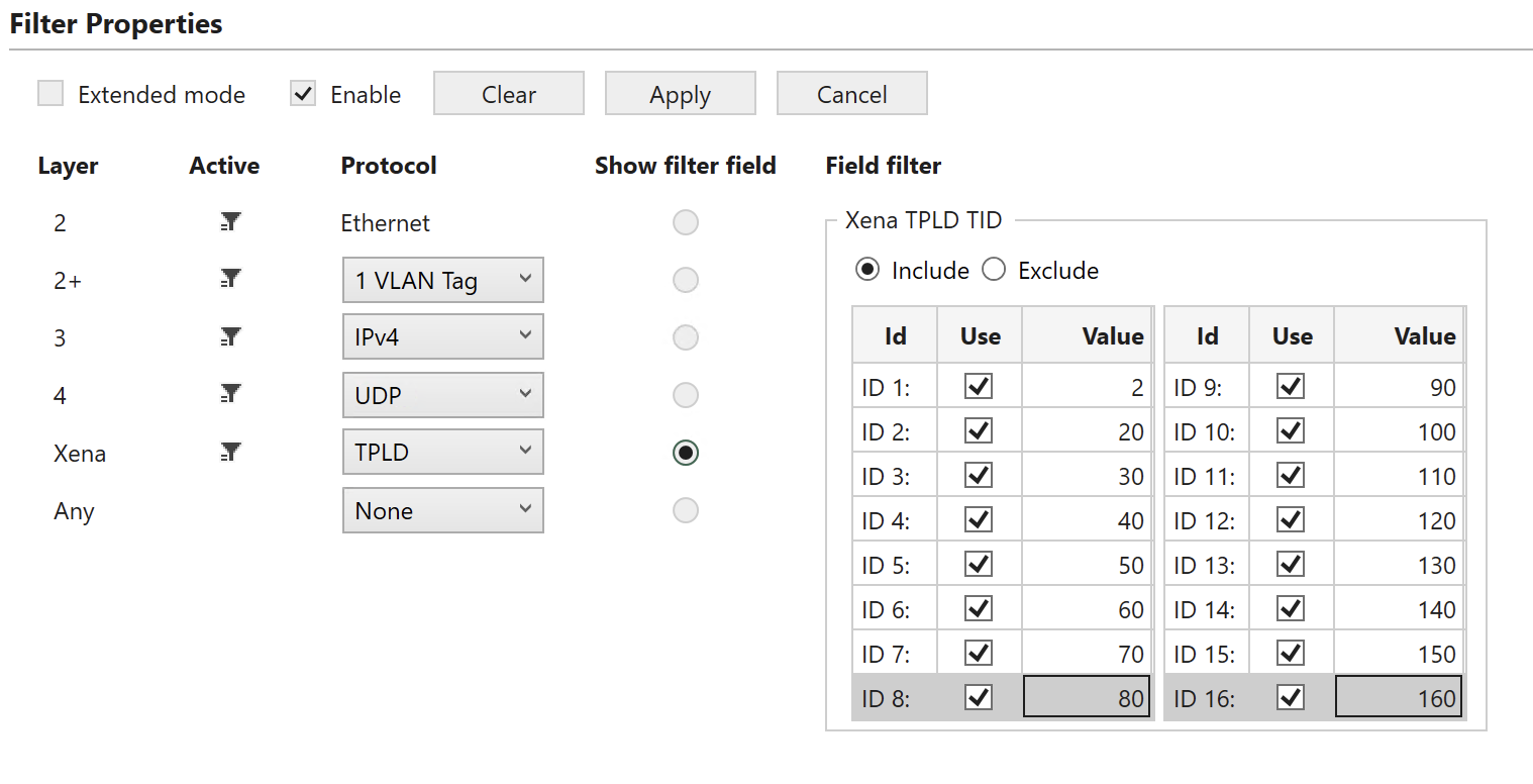
Fig. 6.27 TLPD sub-filter.
To filter based on the TPLD TID, check the Use checkbox and fill in the required TID value. Valid values for the TPLD TID are 0 to 2015 for default size (1023 for Micro) and must match what is configured in the Xena traffic generator.
Note
Configuring multiple TPLD TID values is done by configuring a TID value for multiple indices (Index 0 to 15). The example below illustrates how to filter for packets with TPLD TPID = 987 (index = 5).
PEF_TPLDSETTINGS [fid,0]   AND (1) INCLUDE (1)
PEF_TPLDCONFIG   [fid,0,5] ON (1) 987
PEF_ENABLE       [fid,0]   ON (1)
PEF_APPLY        [fid]
Any Field Sub-Filter
This filter can match 6 consecutive bytes at a configurable offset within the incoming packets. Furthermore, there is a mask to indicate which bits are to be used for matching.
Notice that in addition to the byte match configured here, the packet must match any encapsulation defined in sections 7.1 to 7.4. The available UI configuration options for Any Field filtering are illustrated in Fig. 6.28.
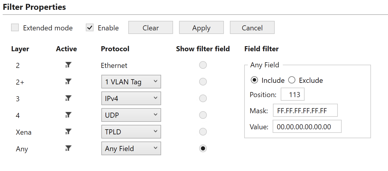
Fig. 6.28 Any Field filtering.
Parameter Position means byte offset in packet. Its range is from 0 to 122, step size is 1.
Note
The example below illustrates how to filter for packets including a 6 bytes value of 0x112233445566 starting at a byte offset of 113 (All bits used for matching).
PEF_ANYSETTINGS [fid,0] AND (1) INCLUDE (1)
PEF_ANYCONFIG   [fid,0] 113 0x112233445566 0xFFFFFFFFFFFF
PEF_ENABLE      [fid,0] ON (1)
PEF_APPLY       [fid]