6.4. Port Properties
This section describes settings which will affect the entire port, i.e. it will affect all the flows defined for the selected port.
6.4.1. Reed-Solomon Forward Error Correction (RS-FEC)
Chimera ports support RS-FEC for 25G and 100G speeds.
To configure RS-FEC on a port, select the port in the UI and go to the tab as illustrated in Figure 8 and click the Enable RS-FEC option.
Note
Note that Link Training and Autoneg are currently not supported for Chimera.
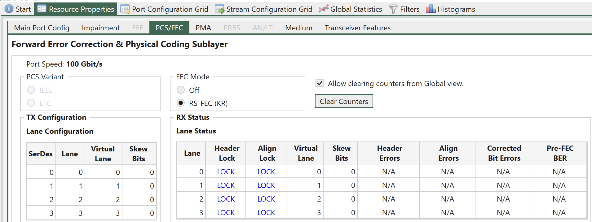
Fig. 6.6 Enable RS-FEC on Chimera port
Note
Corresponding CLI command: PP_FECMODE
6.4.2. Test Payload (TPLD) Size
The Xena traffic generators support inserting a Test Payload (TPLD) into the transmitted packets (see Xena Test Payload ). The TPLD contains meta data, which can be used by the Xena receiving device to provide miscellaneous statistics. When Chimera is connected to a Xena traffic generator, Chimera can use the TPLD in the incoming packets for flow filtering (see section 7.5).
The TPLD supports 2 sizes:
Default (20 bytes)
Micro (6 bytes)
To use the TPLD for filtering in Chimera, it must be configured for the same TPLD format, as the transmitting Xena traffic generator.
Fig. 6.7 illustrates how to configure the TPLD size for a selected port.
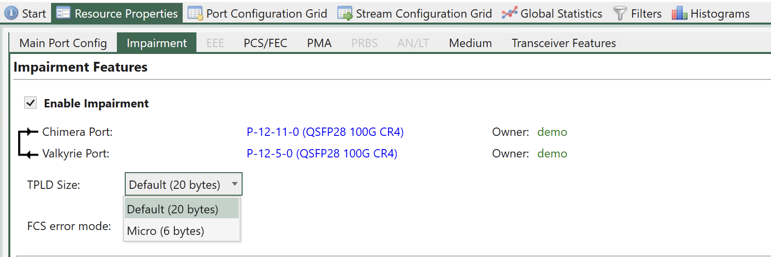
Fig. 6.7 TPLD format configuration.
Note
Notice that this setting is common to all flow filters on this port.
Note
Corresponding CLI command: PE_TPLDMODE
6.4.3. FCS Error Mode
When packets with an FCS error is received on a Chimera port, they are counted by the port statistics as illustrated in Fig. 6.8.
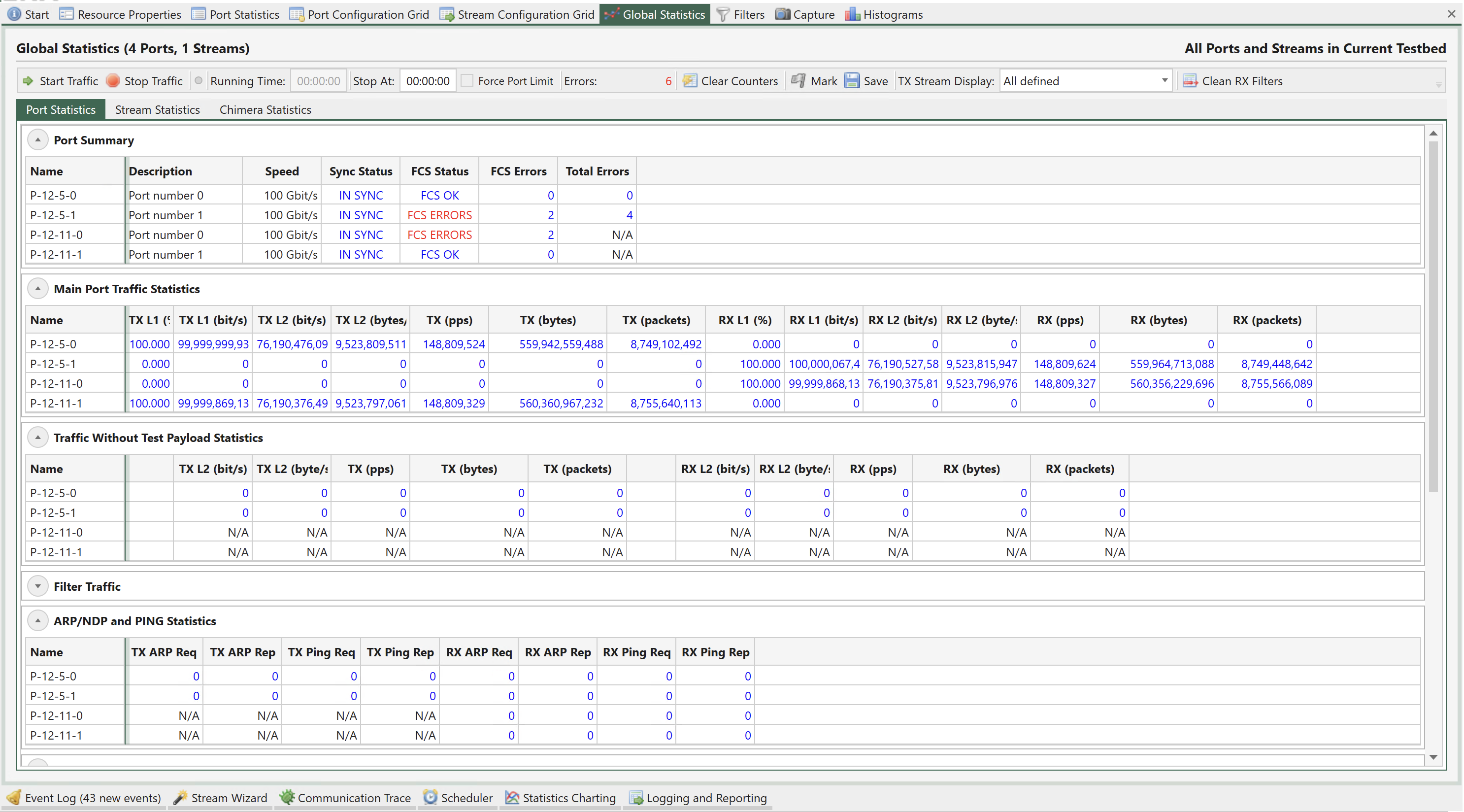
Fig. 6.8 Chimera FCS errors port statistics.
Chimera supports two FCS error modes:
Pass mode
In this mode FCS errored packets are processed by Chimera as any other packet, i.e., the flow filter is a applied and the packet is subject to flow impairment and forwarded onto the output port.
Discard mode
In this mode FCS errored packets are filtered by the flow filters and mapped to the corresponding impairment flow, where they are discarded and counted as OTHER DROPS, as shown in Fig. 6.9.
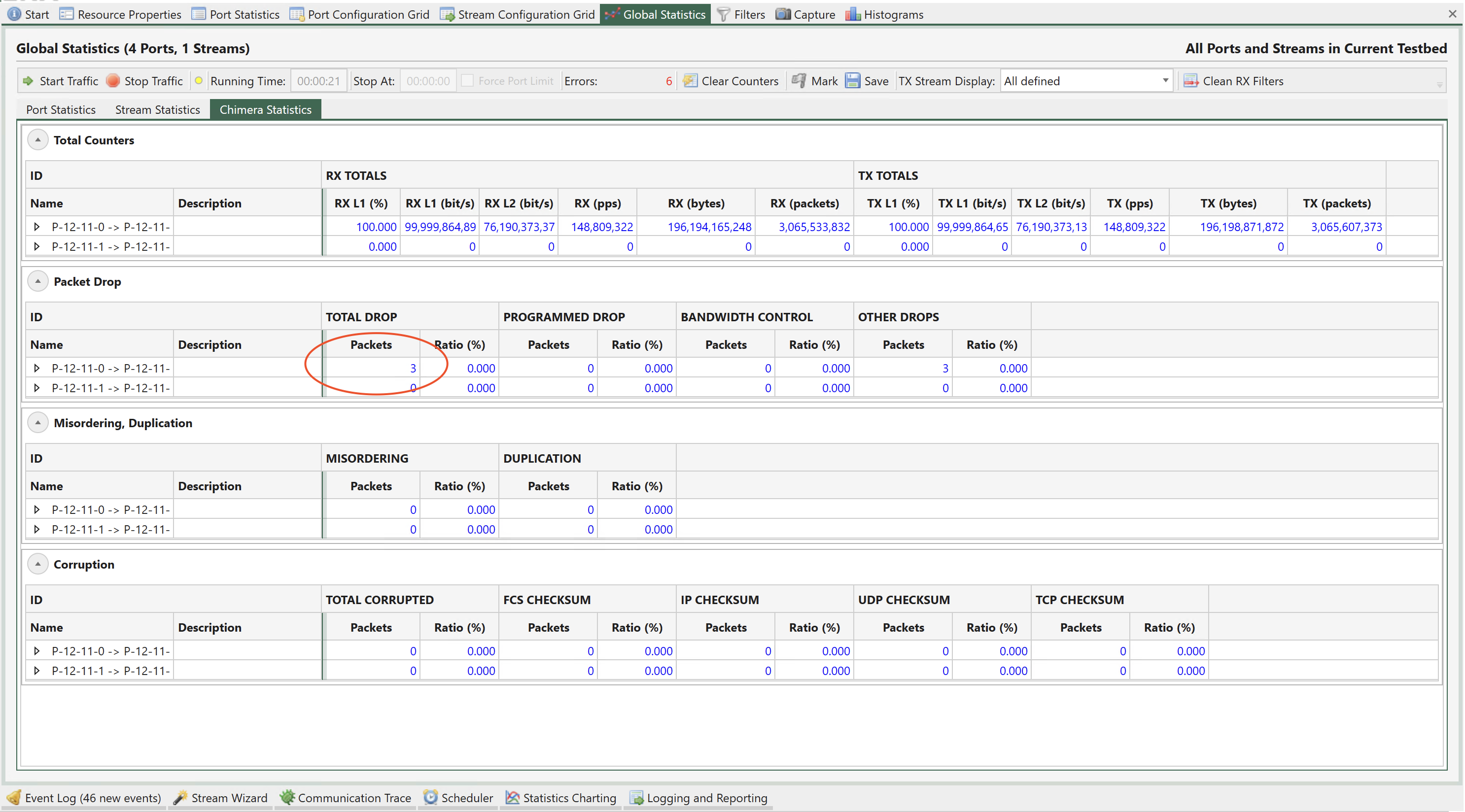
Fig. 6.9 FCS errored packets are discarded as OTHER DROPS
Fig. 6.10 illustrates how to configure the FCS error mode for a selected port.
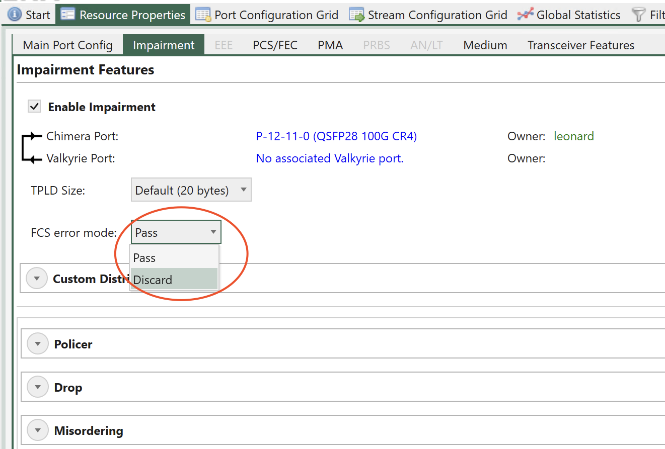
Fig. 6.10 Chimera FCS error mode
Note
Corresponding CLI command: PE_FCSDROP
6.4.4. Link Flap
Chimera can be configured to emulate that the physical link is down or unstable. This feature is called Link Flap. Link flap is implemented in 2 ways: Logical Link Flap and Optical Link Flap.
Notice that link flap is configured at a port level and will affect all flows configured for the selected port.
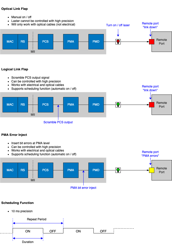
Fig. 6.11 Port impairments
Note
Note that logical link flap and PMA error pulse inject (see Section PMA Error Pulse Injection) are mutually exclusive.
Logical Link Flap
Logical link flap is implemented by scrambling the Tx PCS encoding to prevent the peer port from getting a link. It is not implemented by turning the physical transmitter on or off.
Logical link flap works for both electrical cables (DAC cables) and optical cables.
Logical link flap is configured under the Main Port Config tab as illustrated in Fig. 6.12.
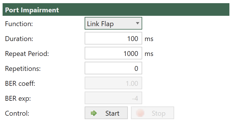
Fig. 6.12 Configuration of Logical Link Flap.
Logical link flap supports a repetitious pattern, where the link is taken down for a period (Duration) and then brought up again. This is repeated after a configurable amount of time (Repeat Period). The flapping is repeated a configurable number of times or continuously (Repetitions).
Pressing Start will start the configured link flap, pressing Stop will stop any ongoing link flapping.
Logical link flap is configured as follows:
Parameter |
Description |
|---|---|
Duration |
Duration of the link flap. |
Repeat Period |
Period after which to restart link flap. |
Repetitions |
How many times to restart the link flap. |
Note
For valid parameter ranges please refer to XOA CLI Documentation.
Note
The example below illustrates how to configure a link flap pattern, which will bring down the link for 120 ms and repeat this every 1.2 sec. This will be repeated 2346 times.
PP_LINKFLAP_PARAMS 120 1200 2346
PP_LINKFLAP_ENABLE ON
Optical Link Flap
To simulate the event of the optical link going down, it is possible to manually turn the optical transmitter off and on.
Optical link flap only works for optical cables, i.e., it will not work with DAC cables for instance. Optical link flap does not support repetitious patterns as described above for logical link flap.
Optical link flap is configured on the Main Port Config tab as illustrated in Fig. 6.13.
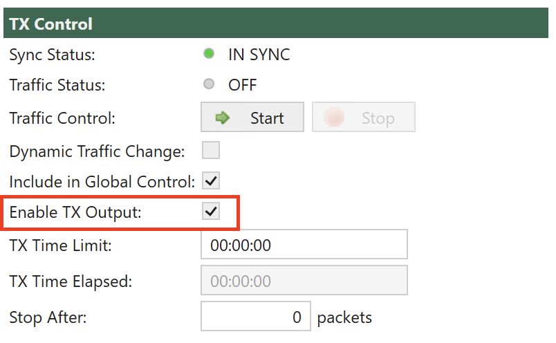
Fig. 6.13 Configuration of Optical Link Flap.
Use Enable Tx Output to turn the optical transmitter off / on.
Note
The example below illustrates how to turn the optical transmitter on and off.
P_TXENABLE OFF
P_TXENABLE ON
6.4.5. PMA Error Pulse Injection
PMA error pulse allows the user to insert pulses of bit errors onto the link. If FEC is enabled, PMA errors are injected after the addition of the FEC bits, so that at the receiving end, FEC will correct as many of the PMA errors as possible.
Notice that PMA error pulse is configured at a port level and will affect all flows configured for that port. For BER insertion on a specific flow, see section 11.1.6.
Logical link flap (see Section Logical Link Flap) and PMA error pulse inject are mutually exclusive.
PMA errors can be inserted with a fixed distance dependent on the selected port speed. The supported distances between two adjacent PMA errors and the corresponding BER for all speeds are listed in Table 6.8, where n is an integer number.
Speed |
Supported PMA error distance |
Supported PMA bit error rate |
|---|---|---|
25G / 10G |
n * 256 bits |
0.39 % / n |
50G |
n * 512 bits |
0.20 % / n |
40G / 100G |
n * 1024 bits |
0.10 % / n |
When PMA pulse error injection is configured, the actual BER applied to the link is rounded to the value of n, which is closest to the configured value.
PMA error pulse injection is configured under the Main Port Config tab as illustrated in Fig. 6.14.
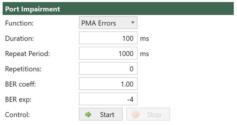
Fig. 6.14 Chimera PMA error pulse injection.
It is possible to configure the length of the error pulse (Duration) and the BER during the pulse (BER coeff and BER exp). The burst is repeated after a programmable period (Repeat Period). The bursts will be repeated a configurable number of times (Repetitions).
Pressing Start will start the configured PMA error pulse, pressing Stop will stop any ongoing PMA error injection.
PMA error pulse inject is configured as follows:
Parameter |
Explanation |
|---|---|
Duration |
Duration of the PMA error pulse. |
Repeat Period |
Period after which to restart the PMA error pulse. |
BER Coeff |
BER coefficient. |
BER Exp |
BER exponent |
Repetitions |
How many times to restart the PMA error pulse. |
Note
For valid parameter ranges please refer to XOA CLI Documentation.
The BER during error pulses is calculated as follows:
BER = coeff / 100 * 10^exp
Note
Notice that the actual BER is rounded to the values listed in Table 6.8.
The example below illustrates how to configure a PMA error pulse inject pattern using CLI PP_PMAERRPUL_PARAMS and PP_PMAERRPUL_ENABLE , which apply PMA errors for 430 ms and repeat this every 2.430 sec. BER = 2.34 * 10e-12. This will be repeated 2346 times.
Duration = 430 (ms)
Repeat Period = 2430 (ms)
BER coefficient = 2.34
BER exponent = -12
Repetitions = 2346
PP_PMAERRPUL_PARAMS 430 2430 234 -12 2346
PP_PMAERRPUL_ENABLE 1