3.1. EPL, Port-Based
In this scenario we will create a simple EPL service with no VLAN multiplexing on the UNI (i.e. port-based) using plain Ethernet traffic.
Add Chassis
Click the Add Chassis button in the main toolbar. This will display the dialog shown below.

Fig. 3.1 Add Chassis button
Enter the IP address and password of a Xena chassis and press OK.
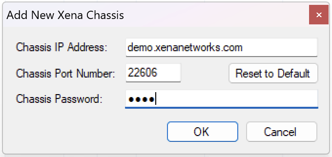
Fig. 3.2 Add Chassis dialog window
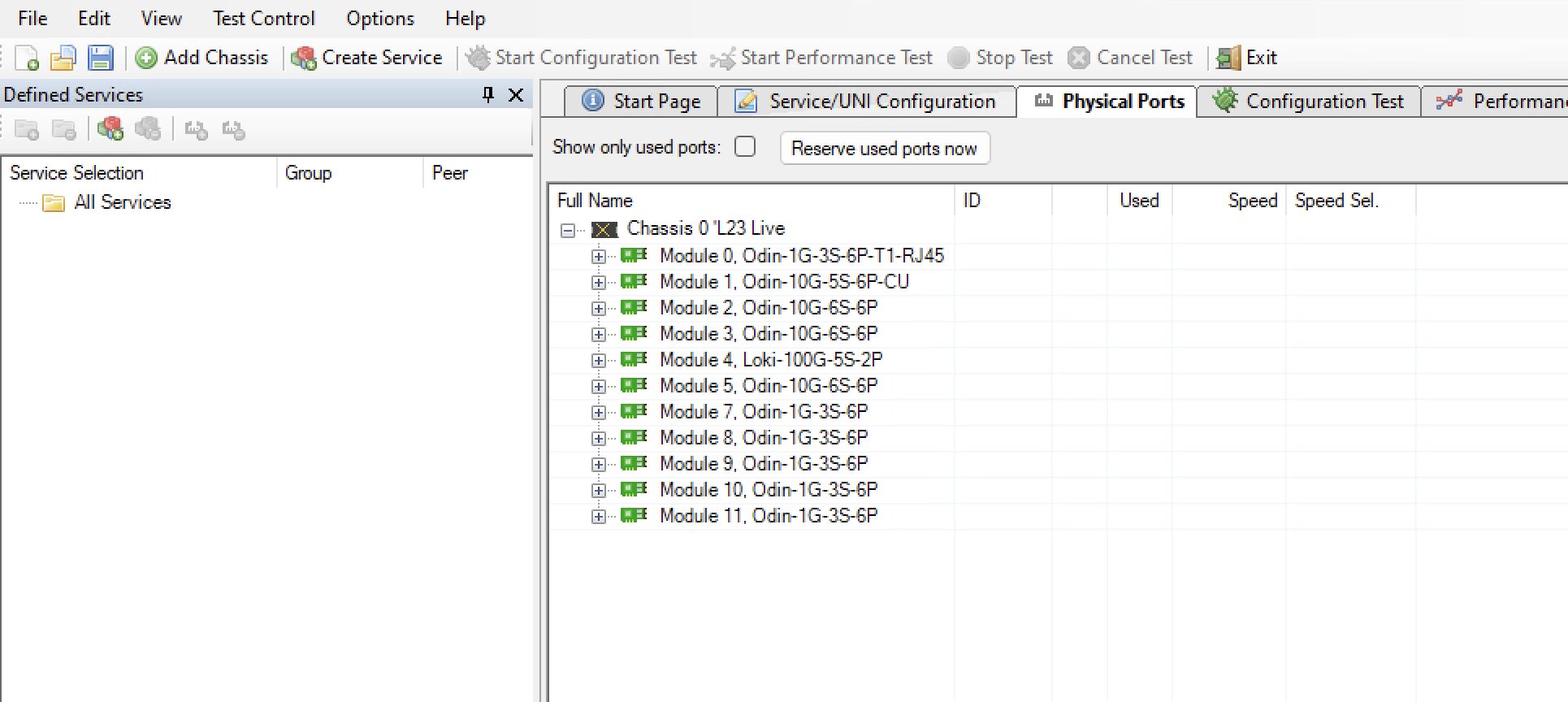
Fig. 3.3 Chassis added
Create Service
Create a new Ethernet service either by clicking the Create Service icon in the small toolbar at the top of the Defined Services tree panel, located at the left part of the application, or by right-clicking on the All Services root in the Defined Services tree panel and selecting the Create Service menu option. This will display the dialog shown in the image.
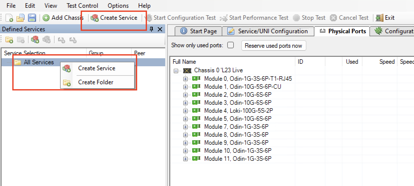
Fig. 3.4 Create Service
Enter a suitable label for the service to make it easy to identify it later on.
Set the Service Type to EPL (should be the default choice). Leave the Is Virtual Service checkbox unchecked as we want to define a port-based service.
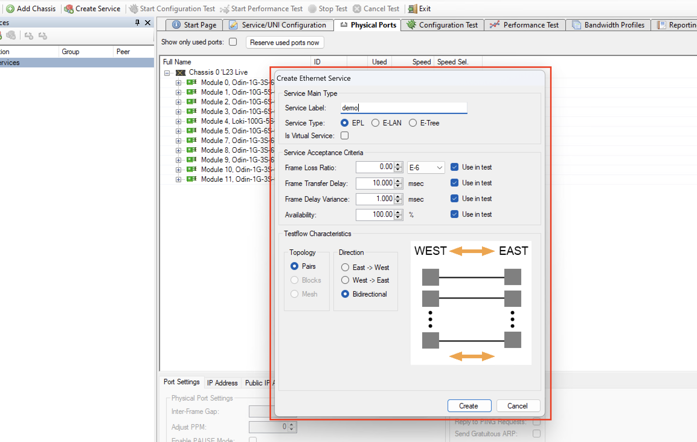
Fig. 3.5 Create Service dialog - EPL
Optionally modify the Service Acceptance Criteria to use in the test. These values represents the guarantees you want to issue to the user of the service as part of the Service Level Agreement (SLA) for this service. If one or more of the criteria should not be used in the test you can deselect them using the Use in test checkboxes to the right.
Finally you need to specify the Testflow Characteristics. For an EPL you can only select the Pairs topology as the other topology options are only relevant for multipoint configurations. You can however select the direction for the test traffic. You should keep the default choice of Bidirectional for this test.
Press the EPL``Create button to create your service.
Create Bandwidth Profile
Switch to the Bandwidth Profiles panel and click the Create Profile button in the small toolbar at the top of the panel. A new entry will now be inserted in the list below. If you cannot see the Bandwidth Profiles panel tab in the tabbed view you can either enlarge the main window until the tab pops into view or you can select the Bandwidth Profiles menu item in the View menu. Alternatively you can click on the little down-arrow in the right edge of the tab-bar and select the Bandwidth Profiles panel.
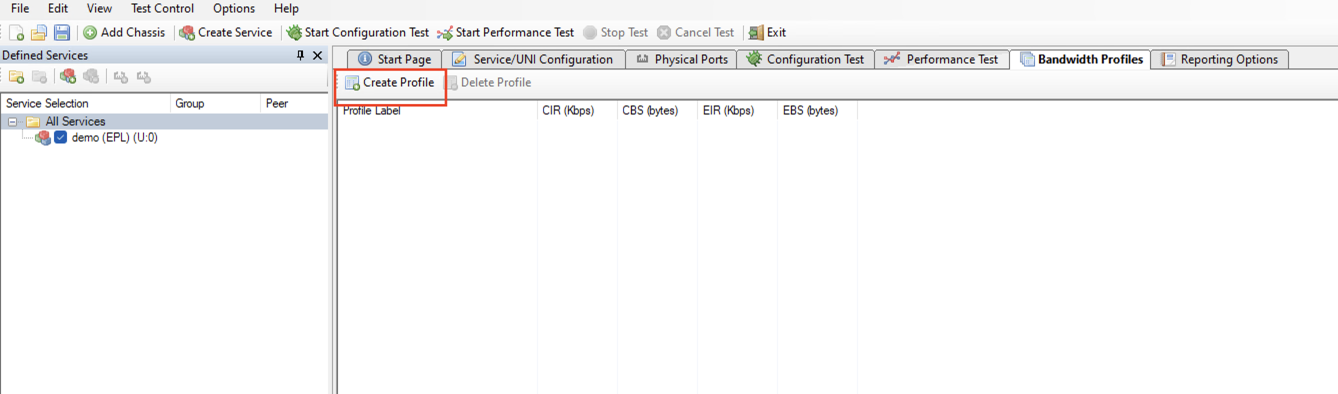
Fig. 3.6 Create Bandwidth Profile
Click the cell in the CIR column and enter the committed bandwidth you want the UNIs to provide.
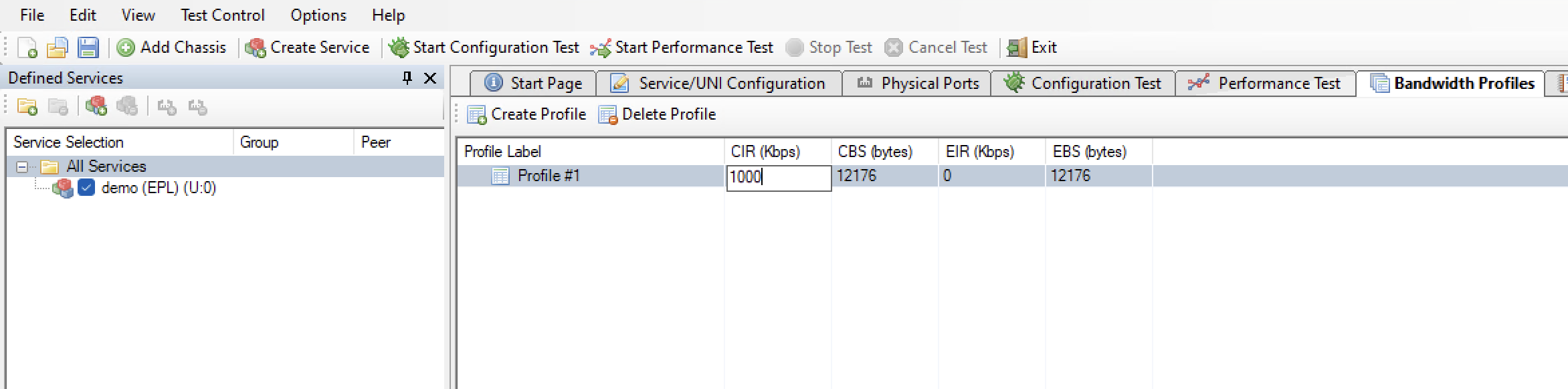
Fig. 3.7 Edit Bandwidth Profile
Optionally click the cell in the EIR column and enter the additional excess bandwidth you want the UNIs to provide.
You can also optionally modify the CBS and EBS values. The default value for both is 12176, according to MEF 13, clause 36.
Add UNIs
Switch to the Physical Ports panel. Expand the module(s) as needed and locate two ports that you want to use in your test.
Select the ports, either one by one or both at the same time, drag them to the service you created in the Defined Services tree view and drop them onto the service.
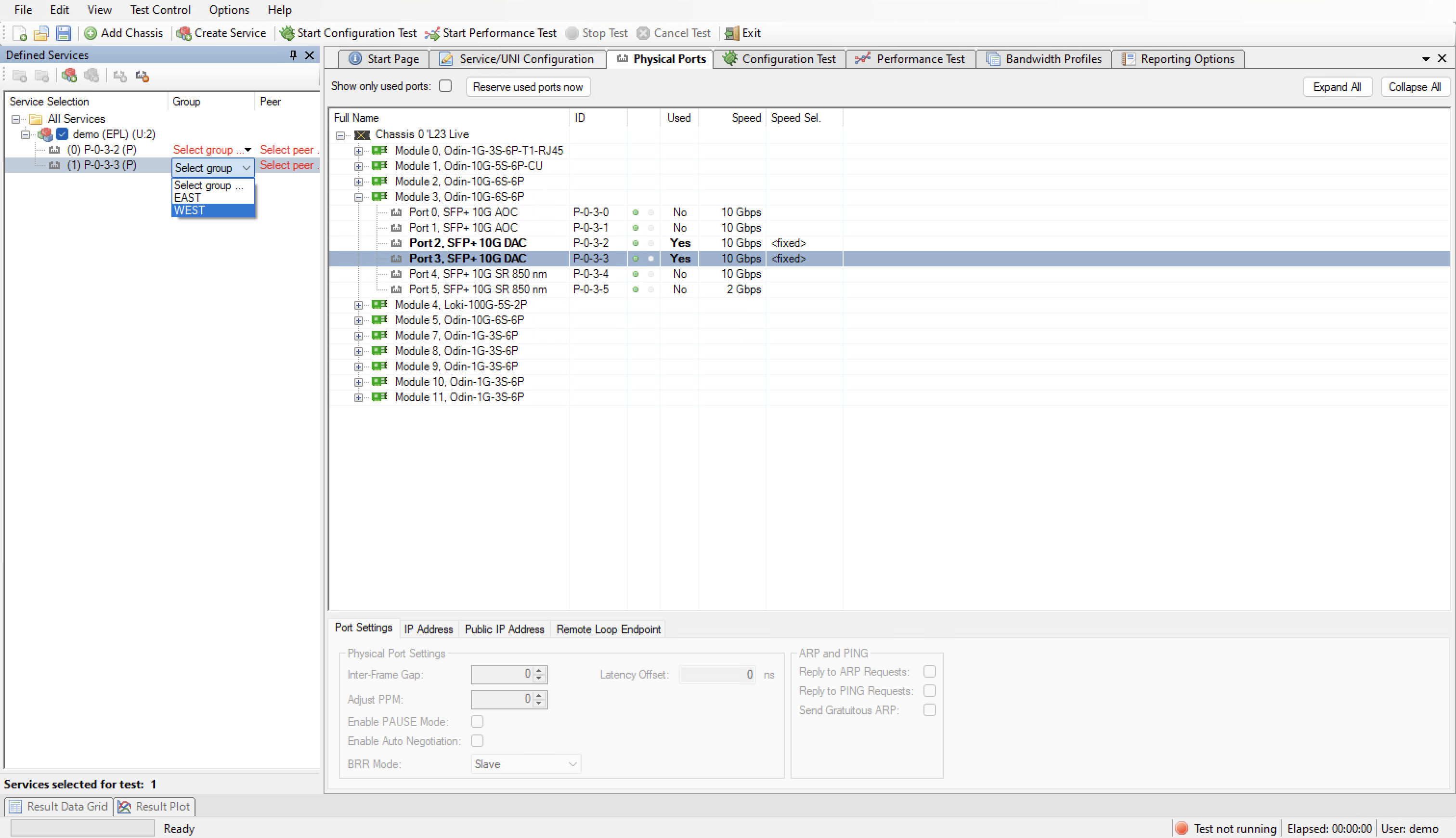
Fig. 3.8 Drag and drop ports to service
The two UNIs will now be shown under the service in the services tree view. Notice that the cells under the Group column contains the text Select Group…. Change this value to EAST for the first UNI and WEST for the other.
Switch to the Service/UNI Configuration panel. Select the first UNI to view the UNI configuration panel as shown below.
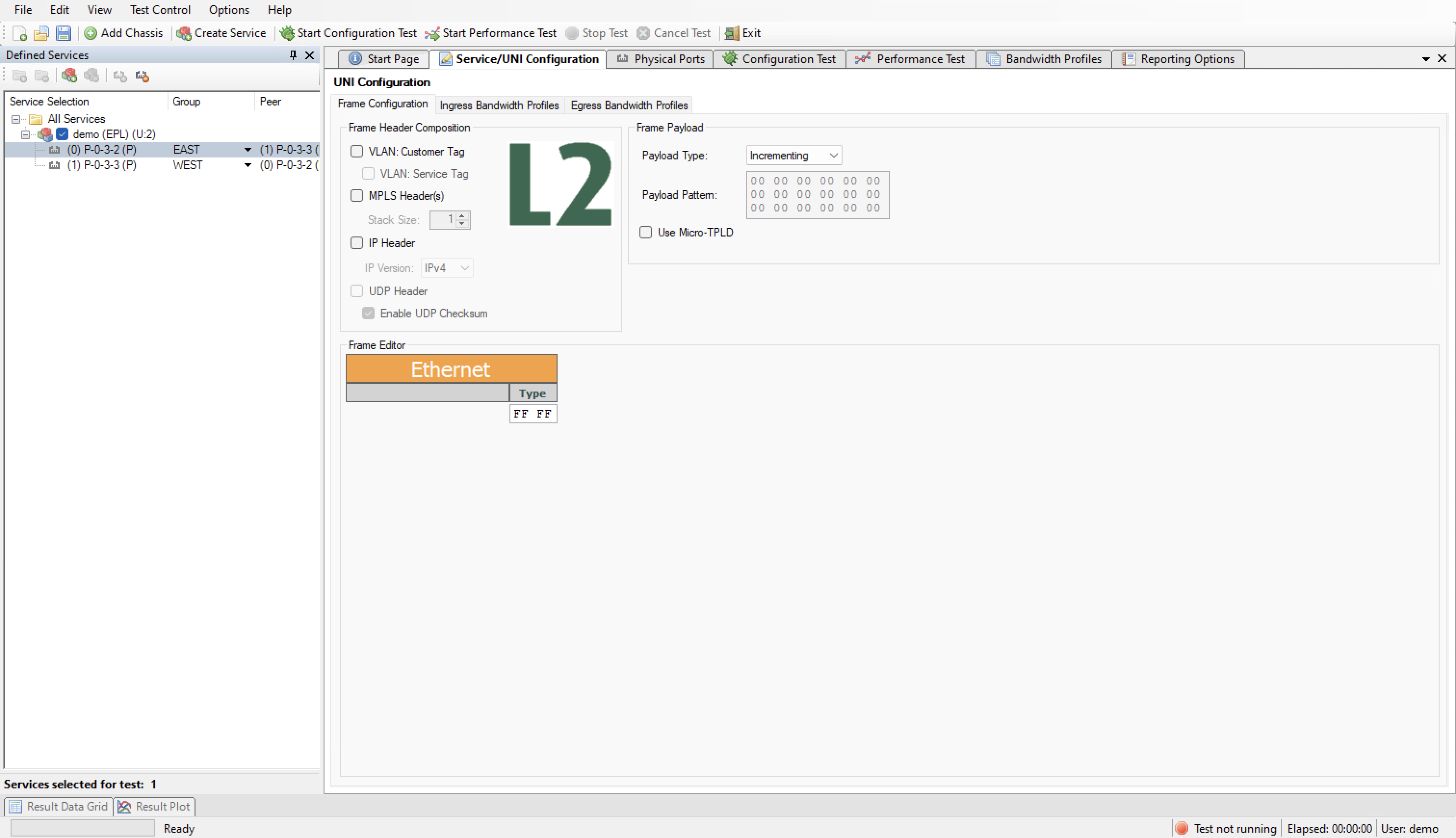
Fig. 3.9 Service UNI panel
For this test we will just leave the default traffic settings (plain Ethernet, no VLANs, no IP, etc).
Select the Ingress Bandwidth Profiles sub-tab and set the Per-UNI Bandwidth Profile to point to the profile we just created.
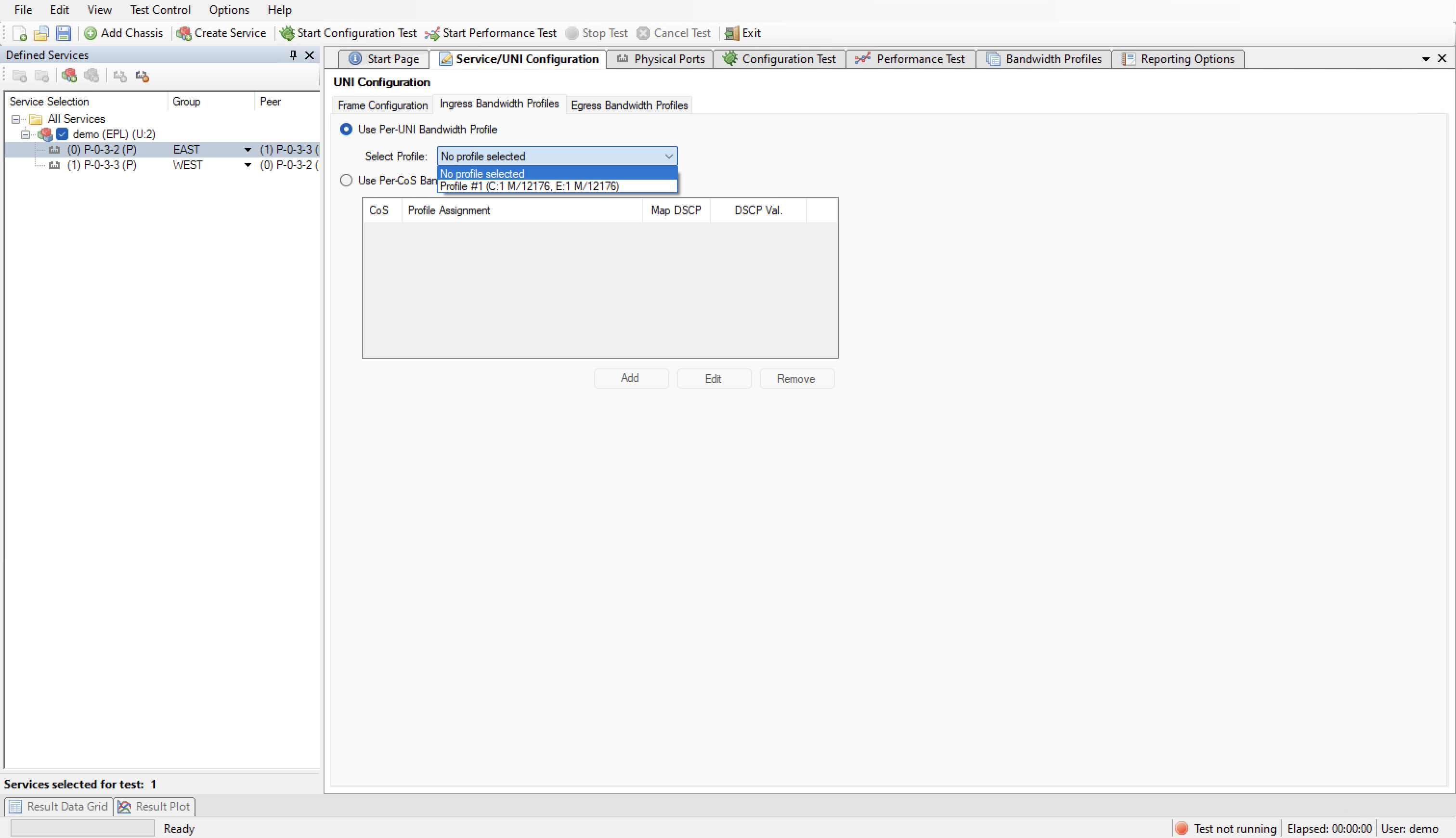
Fig. 3.10 Ingress Bandwidth Profile panel
Do the same for the other UNI.
Save your configuration and give it a suitable filename.
Start Configuration Test
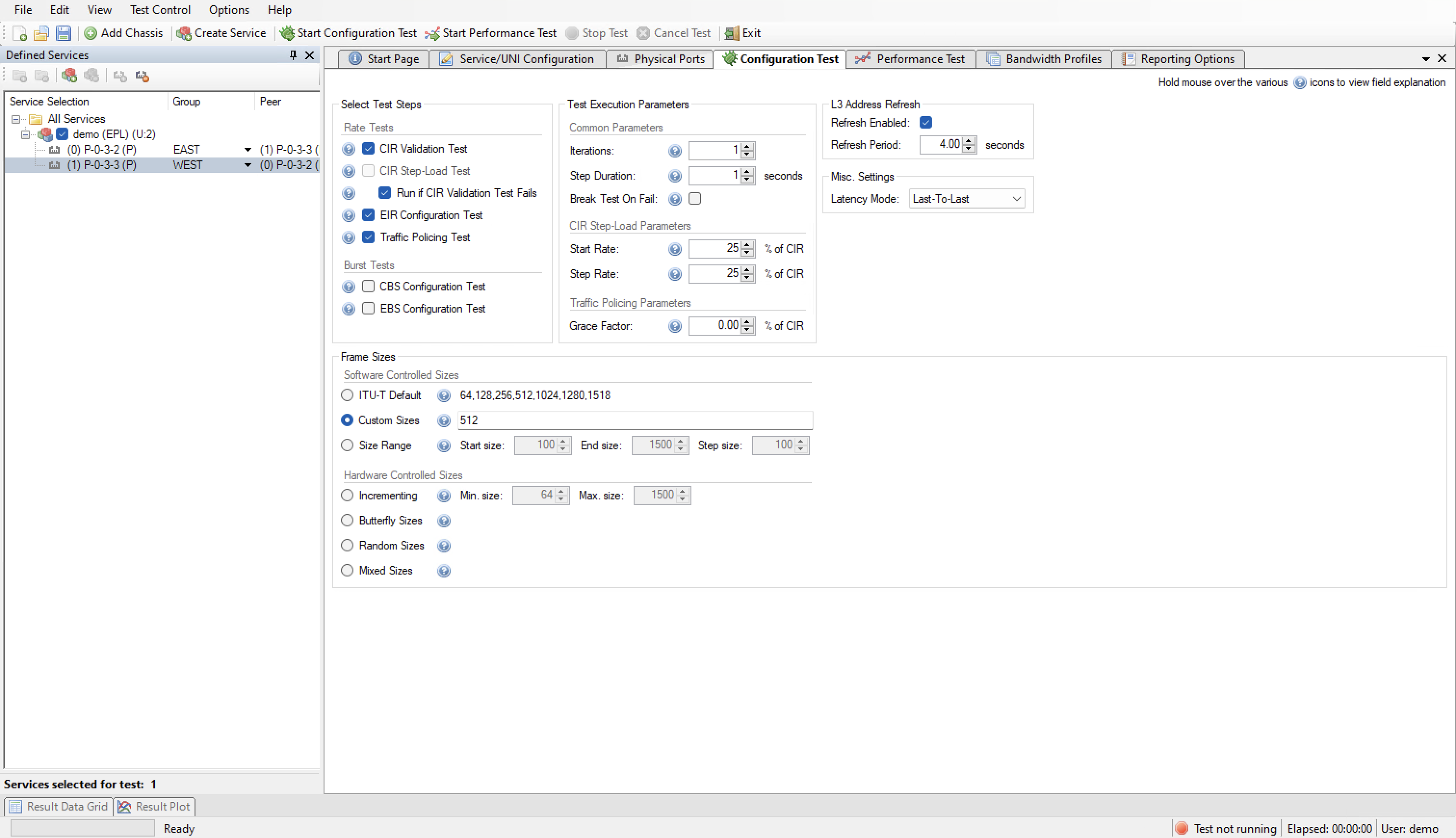
Fig. 3.11 Configuration Test Panel
Click the Start Configuration Test button in the main toolbar.
The Result Data Grid panel will now be shown automatically. Here you can follow the progress of the test.
Once the test completes the resulting PDF report should open automatically in the default PDF viewer application on your PC.
Start Performance Test
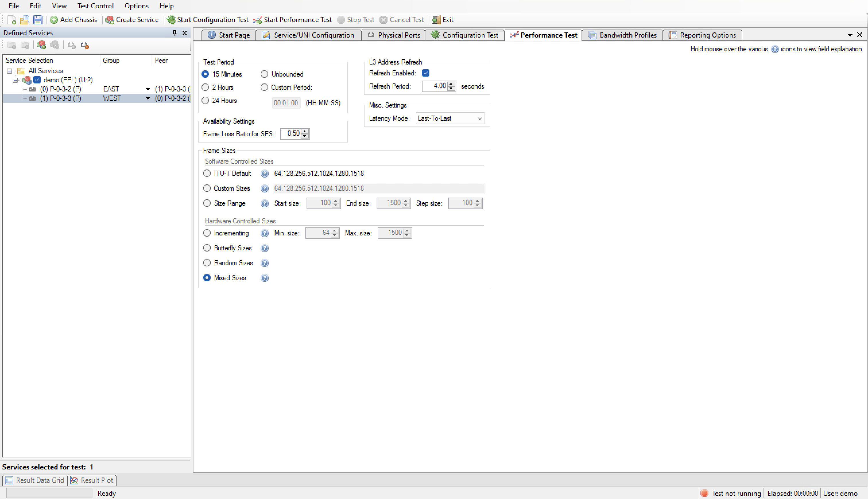
Fig. 3.12 Performance Test Panel
Click the Start Performance Test button in the main toolbar.
The Result Data Grid panel will now be shown automatically. Here you can follow the progress of the test.
Once the test completes the resulting PDF report should open automatically in the default PDF viewer application on your PC.