PCS/FEC
PCS (Physical Coding Sublayer) and FEC (Forward Error Correction) are two essential components of the Ethernet standard that work together to ensure reliable and error-free data transmission over Ethernet networks. These components are primarily associated with the Ethernet physical layer, which is Layer 1 of the OSI model.
FEC Config
PCS Variant
Important
PCS Variant configuration is only available on Z800 Freya module.
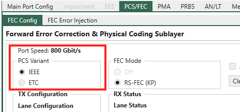
Fig. 79 PCS Variant selection
Both IEEE and ETC (Ethernet Technology Consortium) have specifications for 100 Gb/s serdes lane rate based 800GbE:
IEEE: 800GBASE-CR8/KR8
ETC: 800G-ETC-CR8/KR8
When testing with 800G on Z800 Freya using XenaManager, you can either manually configure the 800G variant by selecting IEEE or ETC in , or let auto-negotiation decide.
FEC Mode
Important
For PAM4 ports, FEC is mandatory.
Depending on the serdes lane speed and port speed, you will see different FEC modes.
For 112G serdes PAM4, 800G/400G/200G port speed, RS-FEC KP is mandatory.
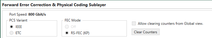
Fig. 80 800G-200G with 112G serdes PAM4. RS-FEC KP is mandatory.
For 112G serdes PAM4, 100G port speed, RS-FEC KP and RS-FEC-Int.
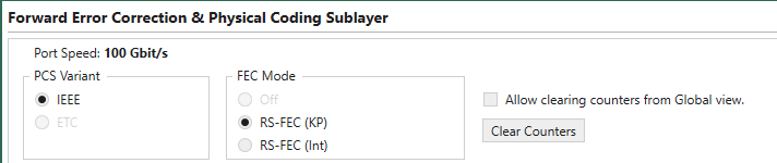
Fig. 81 100G with 112G serdes PAM4. RS-FEC KP and RS-FEC-Int.
For 56G serdes PAM4, RS-FEC KP is mandatory.
Fig. 82 56G serdes PAM4. RS-FEC KP is mandatory.
For 25G serdes NRZ, RS-FEC KR and Off.
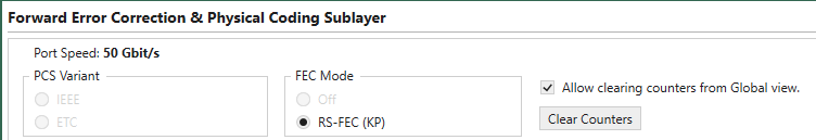
Fig. 83 25G serdes NRZ. RS-FEC KR and Off.
Clear Counters will clear the counters on the page and by checking Allow clearing counters from Global view you can use the clear counters facilities in the Global Statistics pages to clear the counters in this page.
What is shown on the rest of this page depends on the configuration of the selected port.
Lane Configuration & Lane Status
PAM4 Ports (56G and 112G serdes Lane)
The images below show what you can see on a PAM4 port.
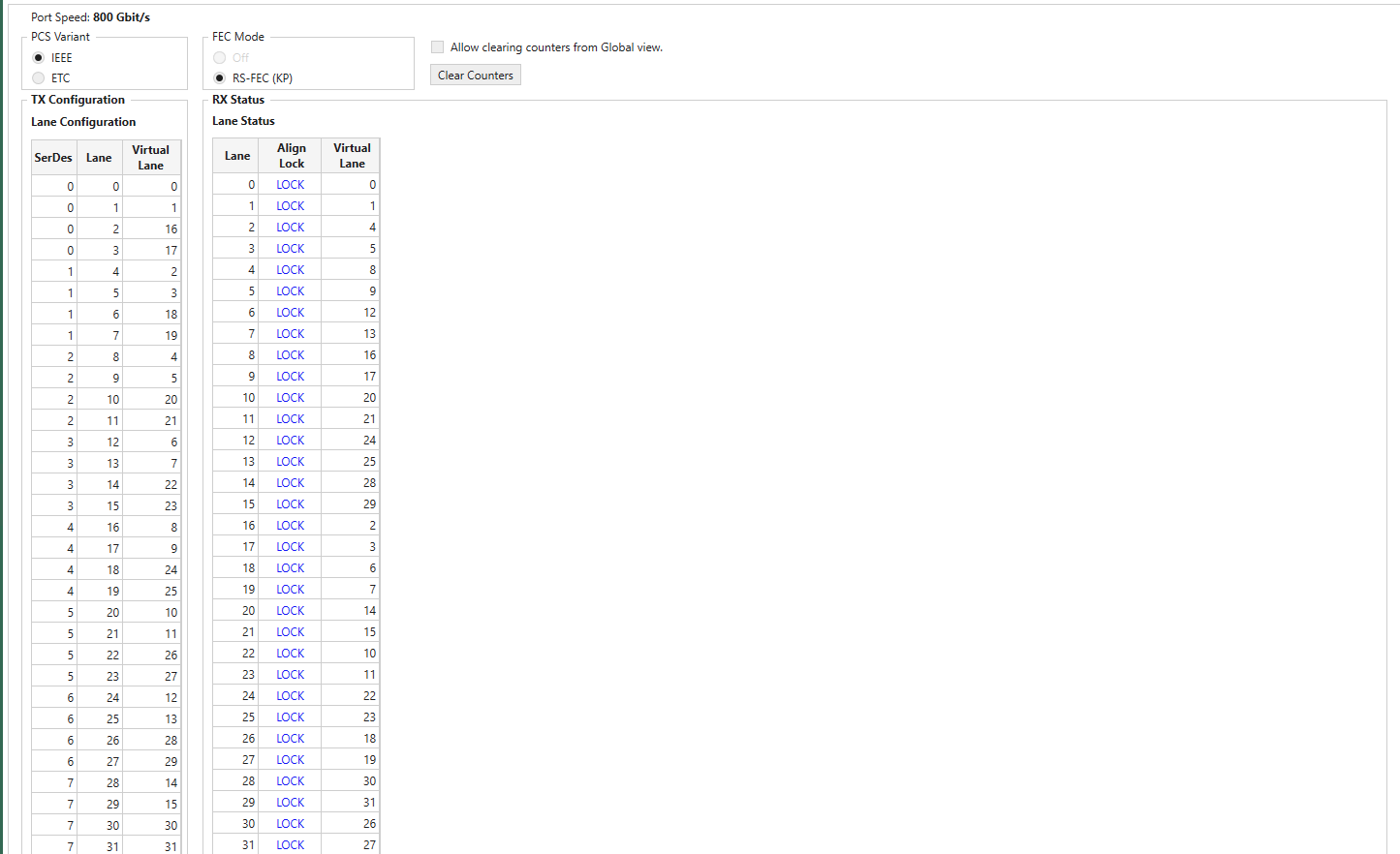
Fig. 84 112G serdes PAM4, 800G port speed on Z800 Freya module. (Only partial screen)
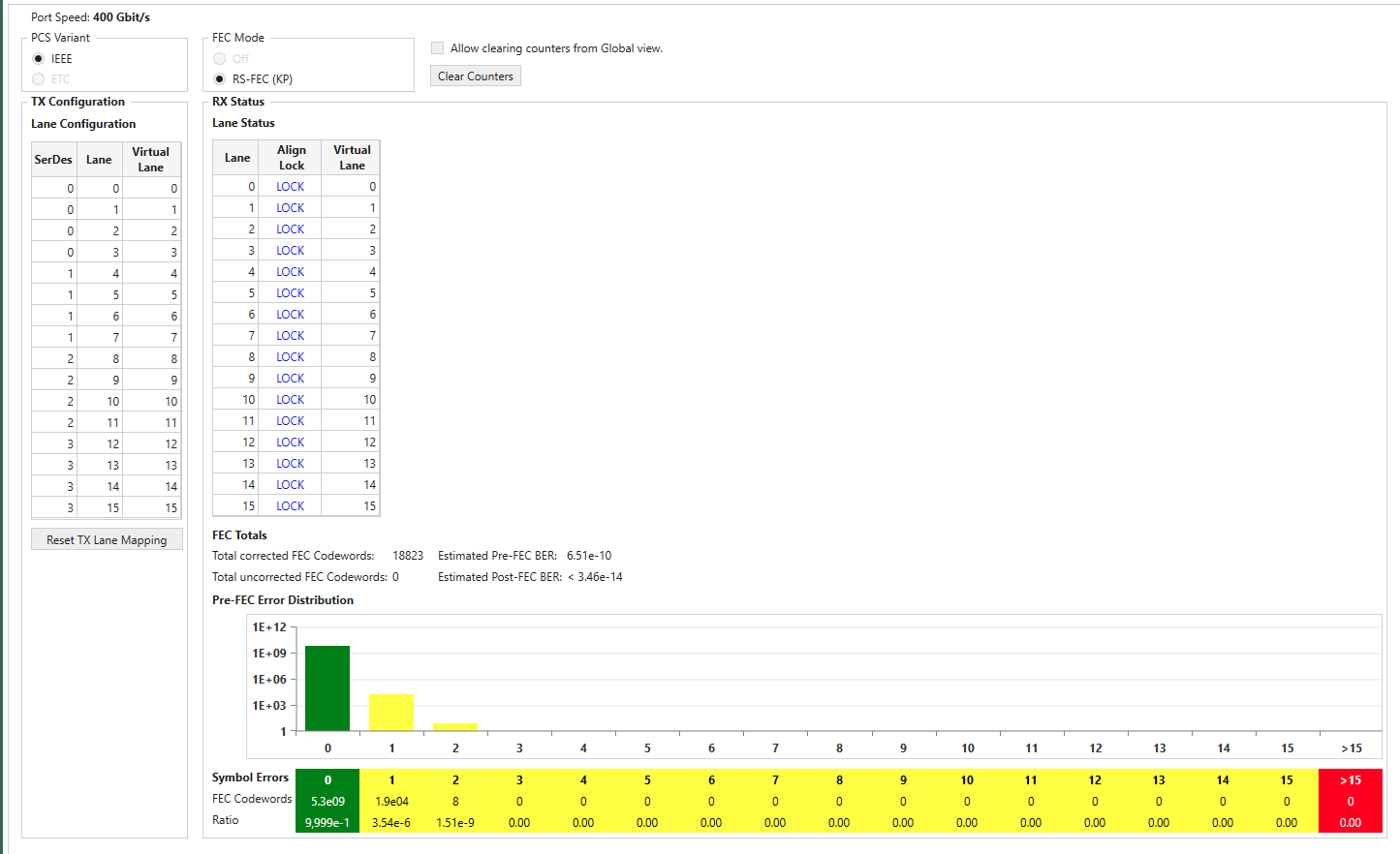
Fig. 85 112G serdes PAM4, 400G port speed on Z800 Freya module.
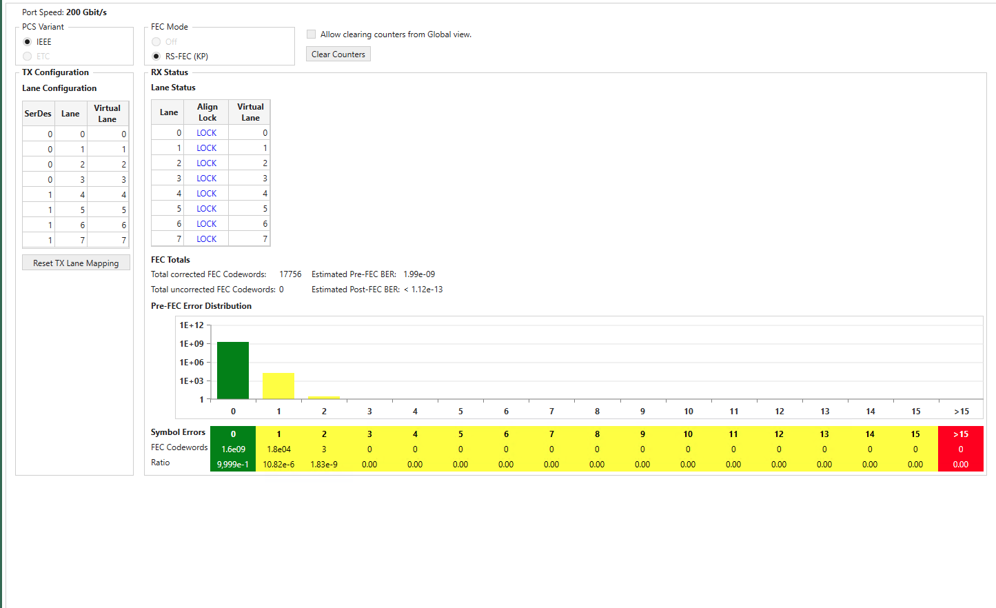
Fig. 86 112G serdes PAM4, 200G port speed on Z800 Freya module.
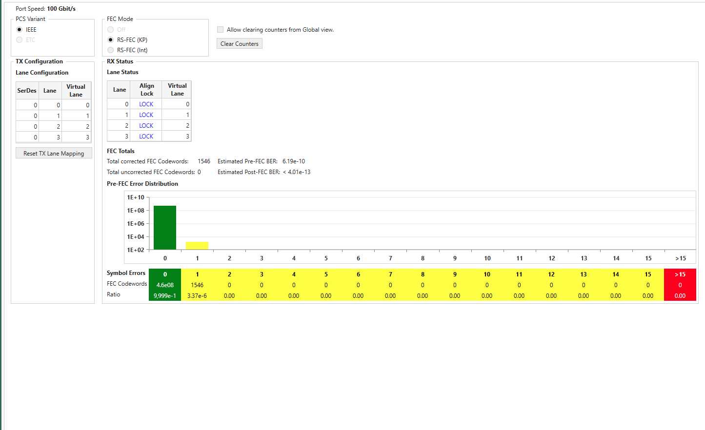
Fig. 87 112G serdes PAM4, 100G port speed on Z800 Freya module.
In the TX Configuration section you can for each physical Lane on the port see the SerDes, and Lane. You can change the Virtual Lane used for the physical lane and set Skew Bits for each lane.
In the RX Status section you can for each physical Lane see if it is in Align Lock (Alignment lock), the Virtual Lane used for the physical lane and set Skew Bits for each lane. In addition, you for each lane can see number of Corrected Bit Errors and the estimated Pre-FEC BER.
The lower part of the page contains FEC statistics for the port:
Total corrected FEC Symbols
Total uncorrected FEC blocks
Estimated Pre-FEC BER
Estimated Post-FEC BER
You will also find the Pre-FEC Error Distribution graph. Here you can see number of received FEC blocks with 0, 1, 2.. up to 15 symbol errors. This is what the RS-FEC used for PAM4 signals will correct. You can also see number of received FEC blocks with more than 15 symbol errors. This is more than the RS-FEC used for PAM4 signals can correct so this will cause uncorrected FEC blocks to be counted and most likely also cause errors at higher layers in the received signal.
Note
Z800 Freya module supports RS-FEC Int, which is specified in IEEE 802.3ck CL 161. When Z800 Freya port is configured to 100GBASE (with 112 serdes speed), the option of RS-FEC Int will be enabled for selection in
NRZ Ports (25G serdes Lane) With FEC
The image below shows what you can see on a NRZ port with FEC, in this case a 100G port.
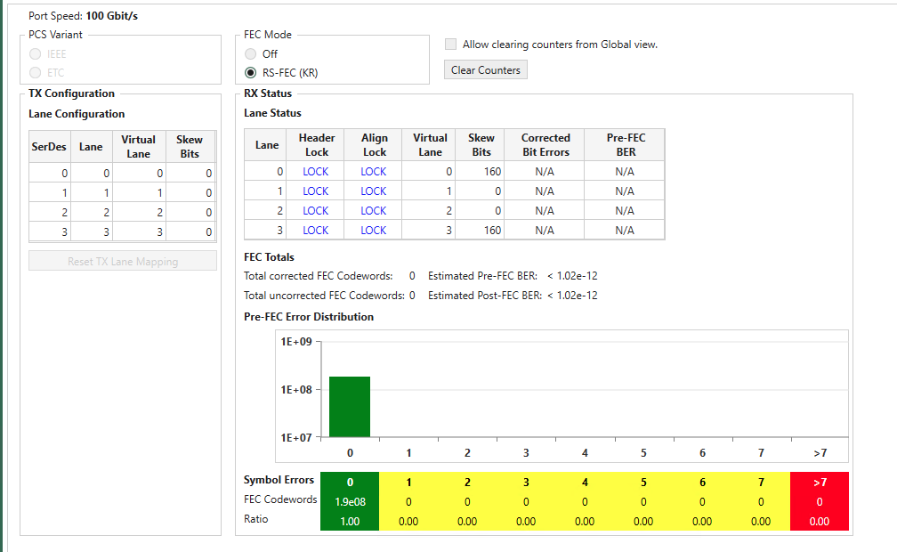
Fig. 88 Port Properties - PCS/FEC - FEC Config (NRZ Ports w/ FEC)
Most is similar to what you can control and see for PAM4 ports. Please also observe that the RS-FEC used for NRZ signals will correct up to 7 symbol errors. The Pre-FEC Error Distribution graph is adjusted accordingly.
Some ports also support Firecode FEC when running at 10G and 25G NRZ.
Note
Port speeds of 10G/25G on Z100 Loki and Z400 Thor support Firecode FEC.
NRZ Ports (25G serdes Lane) No FEC
The image below shows what you can see on a NRZ port without FEC, in this case a 100G port.
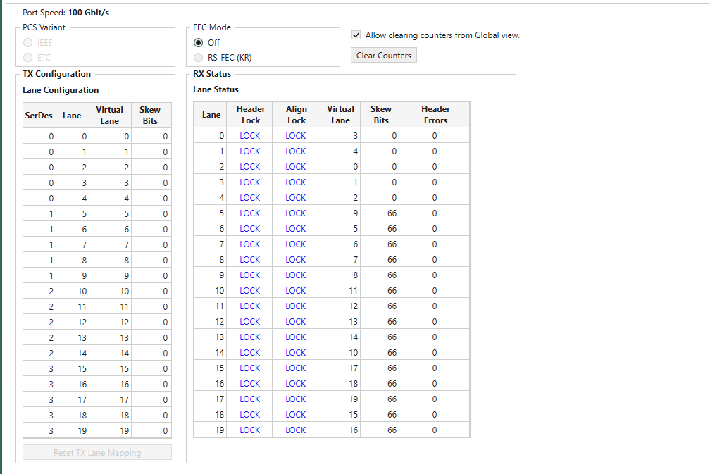
Fig. 89 Port Properties - PCS/FEC - FEC Config (NRZ Ports w/o FEC)
Most is similar to what you can control and see for PAM4 ports in the Transmit Configuration and Receive Status tables. Please observe however that in the Receive Status table you can see additional counters for Header Errors, Alignment Errors. The Corrected Bit Errors and the Pre-FEC BER counters are not updated for ports without RS-FEC.
Note
Port speeds of 10G/25G on Z100 Loki and Z400 Thor support Firecode FEC.
FEC Error Injection
FEC Error Injection feature to Z800 Freya for RS-FEC KP (544,514) and RS-FEC-Int (544,514).
Codeword, Symbol and Bit Errors
FEC is a technique used to detect and correct a certain number of errors in a bit stream by appending redundant bits and error-checking code to the message block before transmission.
FEC uses
nsymbol codewords (CW) consisting of a data block that isksymbols long and a parity block (the code and redundant bits) that is`` n-k`` symbols long. We denote a particular FEC by the ordered pair(n,k).
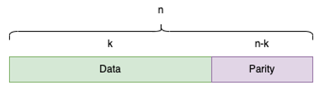
Fig. 90 RS-FEC notation
For RS-FEC KP (544,514) and RS-FEC-Int (544,514), 10 bits form a FEC symbol and 544 symbols a FEC codeword, where 514 of them are data symbols and 30 are parity symbols, as depicted below.
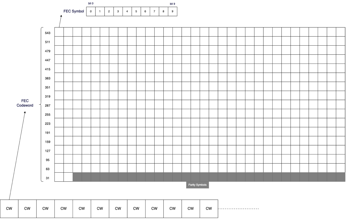
Fig. 91 FEC Codeword, Symbol, and Bit
Codeword & Symbol Error Configuration
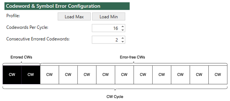
Fig. 92 Injection cycle illustration
On the codeword level, you configure the number of codewords of an injection cycle. The Codewords Per Cycle must be an even integer for 112G SerDes, e.g. 2, 4, 6, 8, etc. Inside a cycle, you can configure the number of Consecutive Errored Codewords, in which at least one errored symbol is injected. As depicted above, the errored codewords are placed before the error-free.
There are two pre-defined profiles you can load:
Max Consecutive Uncorrectable w/o Link Loss
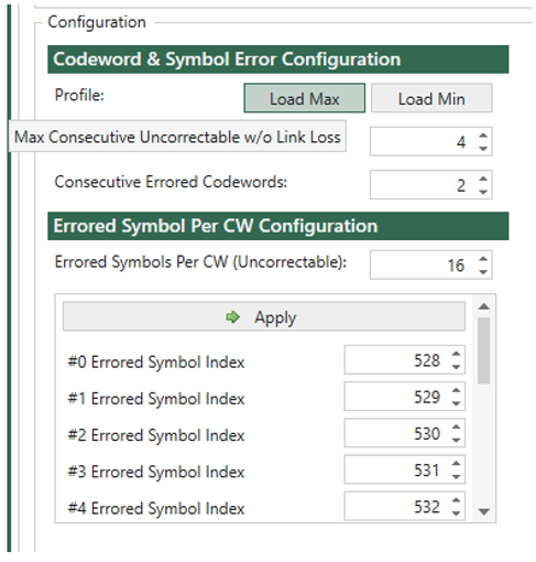
Fig. 93 Load Max Consecutive Uncorrectable w/o Link Loss
Min Consecutive Uncorrectable with Link Loss
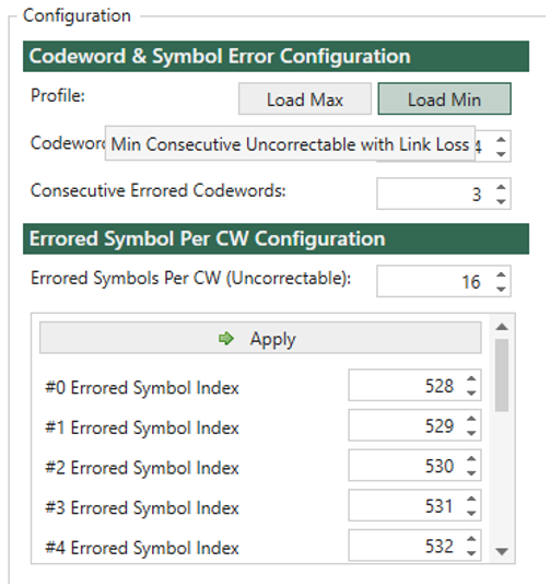
Fig. 94 Load Min Consecutive Uncorrectable with Link Loss
After loading the profile, you can still customize it to meet your test requirements.
Important
You need to click the Apply button to commit the errored symbol index list after loading the profile.
Errored Symbol Per CW Configuration
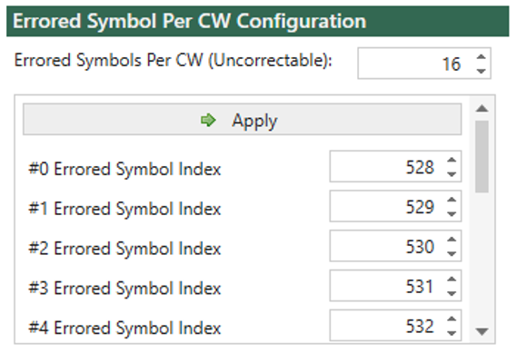
Fig. 95 Errored Symbols Per CW and Errored Symbol List
On the symbol level, you configure the quantity of errored symbols inside an errored CW in Errored Symbols Per CW, and the position of each errored symbol in the list below it.
For RS-FEC KP and RS-FEC-Int, a CW with more than 15 errored symbols is uncorrectable, which you can see as you configure.
Every time the errored symbol index list is changed, you need to click Apply to commit the change to the chassis. If you have many indices to change, you can use the tab key on the keyboard to go from one index to the next, or shift + tab to go back.
Bit Error Mask Configuration
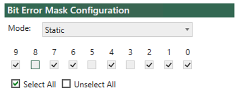
Fig. 96 Bit Error Mask Configuration - Mask Configuration
On the bit level, you configure the quantity of errored bits inside an errored symbol, and their position. Use the bit mask pattern checkbox to select which bits are errored inside an errored symbol. The most significant bit (bit 9) is placed on the left, and the least significant bit (bit 0) on the right.
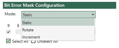
Fig. 97 Bit Error Mask Configuration - Mode
There are three modes you can choose:
Static: The bit error pattern stays the same for all errored symbols.
Rotate: The bit error pattern shifts one bit to the most significant bit per errored symbol.
Increment: When this mode is selected, the bit error pattern is ignored. Instead, the bit error pattern initiates from 000000001, 000000010, 000000011, continuing up to 111111111, and repeating the sequence as 000000001…
Loop Mode
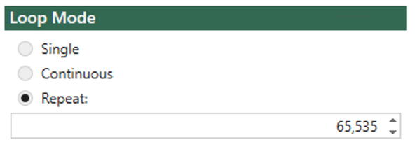
Fig. 98 Loop Mode
There are three loop modes for you to control how many cycles to inject:
Single: Inject a single cycle.
Continuous: continuously inject cycles until explicitly stop.
Repeat: Inject a specific number of cycles (max 65,535)
FEC Engines
Z800 Freya ports in different speeds have different numbers of FEC engines. all FEC engines of a port are enabled. FEC engine selection is not supported yet.
serdes Speed |
Port Speed |
FEC Engines |
112G |
800G |
4 |
400G |
2 |
|
200G |
2 |
|
100G (RS-FEC KP) |
1 |
|
100G (RS-FEC-Int) |
1 |
|
56G |
400G |
4 |
200G |
2 |
|
100G |
1 |
TX Error Injection Statistics
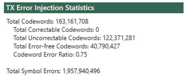
Fig. 99 TX Error Injection Statistics
In the TX statistics, you can find the following counters:
Total transmitted CWs
Total correctable CWs (errored but with <=15 errored symbols)
Total uncorrectable CWs (errored and with >15 errored symbols)
Total error-free CWs
CW error ratio (1-total-error-free/total-cws)
Total transmitted errored symbols
Attention
Each FEC engine injects errors independently according to the configurations. This means the total counters is what you configure on the UI multiplied by the number of FEC engines.