6.7.2. Impairments Types
This section describes the impairments which are configured on a per flow basis. For a definition of flows, see Section Packet Flow.
As described in Section Overview, each impairment can be assigned a set of distributions (see Section Impairments Distributions) and a scheduler (see Section Scheduler Functions). This section will focus on the Chimera impairments, including examples of how to configure selected distributions and the scheduler. However, for an elaborate description of the distributions available for each impairment, see section 11. For an elaborate description of the scheduler.
To enable flow impairments, the impairments must be enabled on the port level. This is illustrated Fig. 6.38.
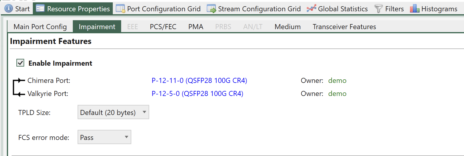
Fig. 6.38 Enable impairments.
If impairments are configured at the flow level but not enabled at the port level, they will not have any effect on the flow.
Note
The following example illustrates how to enable flow impairments on a port.
P_EMULATE ON
To configure the impairments for a given flow, first select the flow to configure using UI. Fig. 6.39 illustrates how to select flow 0 (Port default flow).
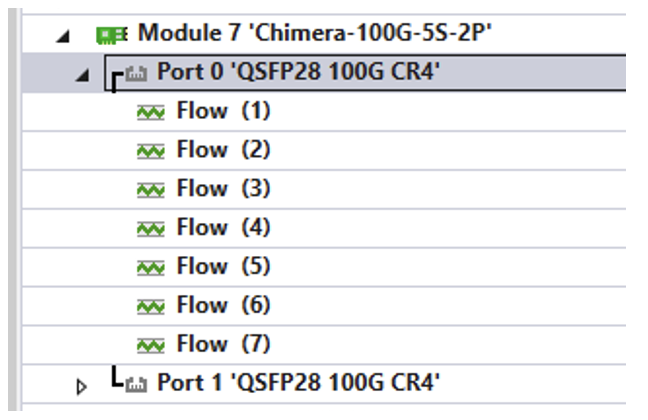
Fig. 6.39 Select flow to configure in the UI.
Then, expand the impairment window for the impairment to configure. The available impairment windows are illustrated Fig. 6.40.
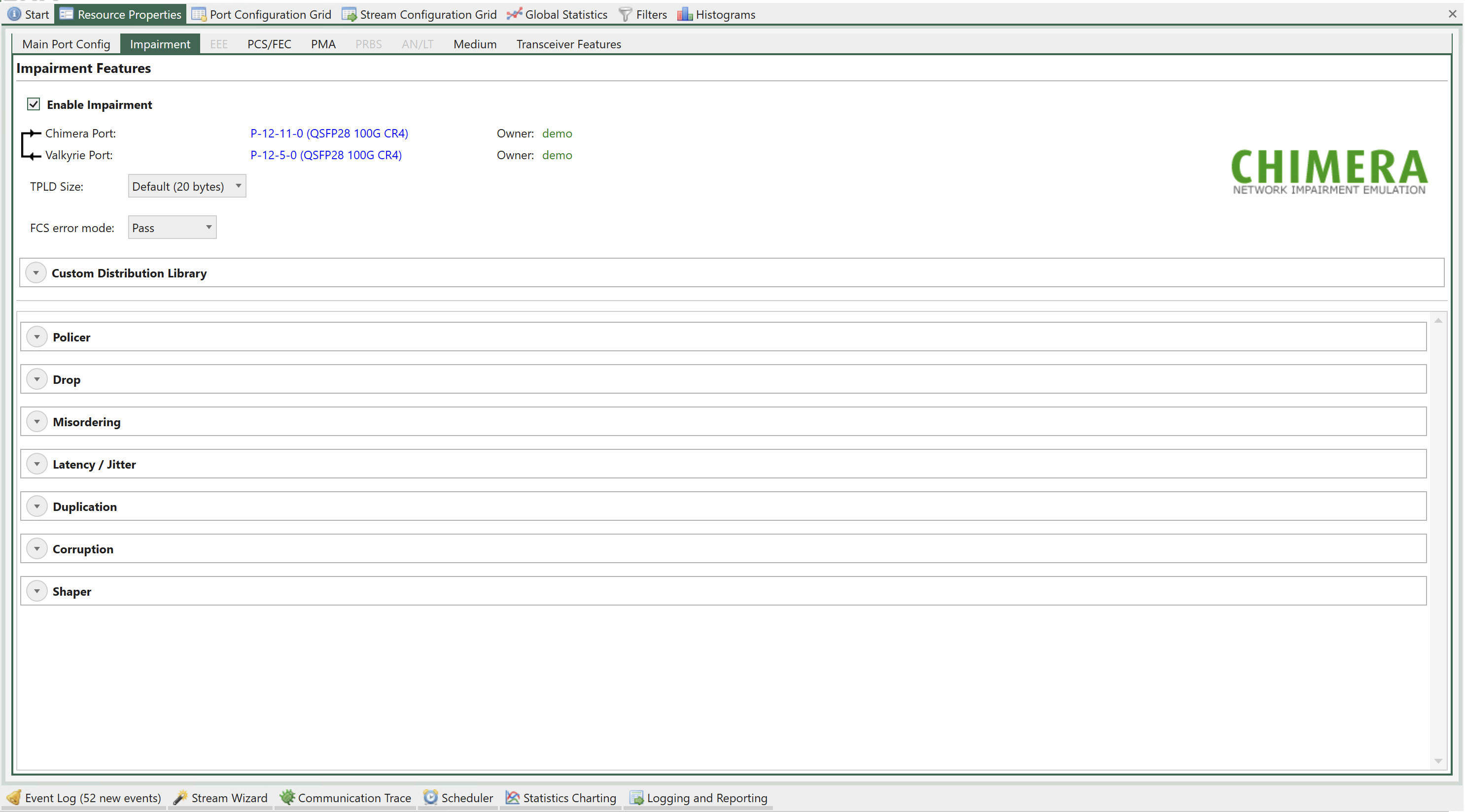
Fig. 6.40 Select impairment to configure in the UI.
The configuration of each impairment is explained in the following sub-sections.
See also
Read more about Impairments Distributions and Scheduler Functions.
Duplication (iid = 3)
Packet duplication will duplicate a packet, so the packet is transmitted twice in the Ethernet packet flow. The duplicate packet is inserted right after the original packet.
Notice that packet duplication is located after the shapers, just before the Tx port in the impairment pipeline. I.e., enabling packet duplication will add packets to the packet flow after the shapers, hereby increasing the BW compared to what was configured in the shaper. For further details on shapers, see section 10.5.
Configuration of duplication using the UI is illustrated Fig. 6.41.
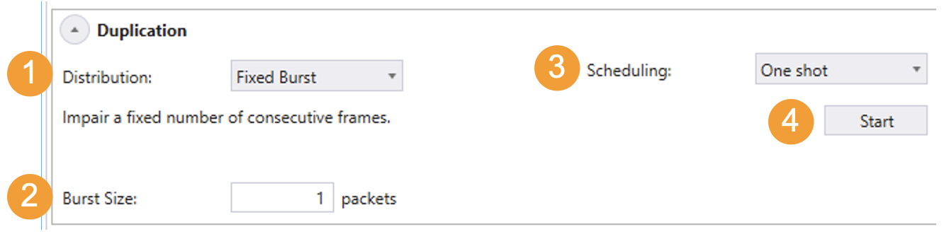
Fig. 6.41 Duplication configuration in the UI.
(There is no configuration of the impairment for duplication.)
To configure duplication:
Select the relevant distribution from the distribution dropdown menu (e.g. Fixed Burst).
Supply the parameters to configure the selected distribution (e.g. Burst Size = 1).
Configure the scheduler (e.g. One shot).
Press Start to activate the impairment.
The configuration shown Fig. 6.41 41 will cause the next packet to be duplicated, implementing a burst of 1 duplicated packet.
Note
For every impairment, distribution Fixed Burst can be used to manually insert a number of consecutively impairments. Simply configure the burst size and press Start.
Note
The example below illustrates how to duplicate a single packet (Schedule = One shot).
PED_SCHEDULE[fid,3]     1   0
PED_FIXEDBURST[fid,3]   1
PED_ENABLE[fid,3]       ON
Packet Drop (iid = 0)
Packet drop will cause packets to be removed from the Ethernet packet flow. Configuration of drop using the UI is illustrated Fig. 6.42.
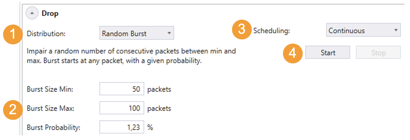
Fig. 6.42 Drop configuration in the UI.
(There is no configuration of the impairment for Drop).
To configure Drop:
Select the relevant distribution from the distribution dropdown menu (e.g. Random Burst).
Supply the parameters to configure the selected distribution. (e.g. Burst Size Min = 50, Burst Size Max = 100 and Burst Probability = 1.23 %.)
Configure the scheduler (e.g. Continuous)
Press Start to activate the impairment.
To stop dropping packets press stop.
The configuration shown Fig. 6.42 will cause a drop burst to start at any packet with a probability of 1.23 %. The size of each burst will be selected randomly between 50 packets and 100 packets.
Note
The example below illustrates how to configure the same configuration using script commands.
PED_SCHEDULE[fid,0]      1  0
PED_RANDOMBURST[fid,0]   50 100 1230
PED_ENABLE[fid,0]        ON
Misordering (iid = 1)
Misordering causes packets to be taken out of the Ethernet packet flow and delayed for a configurable number of packets, after which they are re-inserted into the packet flow. The number of packets that the packet is delayed is referred to as the Misorder Depth.
At any point in time, only a single packet can be in queue to be re-inserted. As a result, the following limitation applies to the values of probability and depth.
The number of distributions which support misordering are limited to:
Fixed Burst with burst size = 1
Fixed Rate
Configuration of misordering using the UI is illustrated Fig. 6.43.
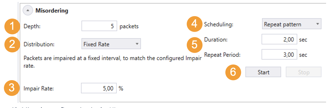
Fig. 6.43 Misorder configuration in the UI.
To configure misordering:
Configure the misordering depth.
Select the relevant distribution from the distribution dropdown menu (e.g. Fixed Rate).
Supply the parameters to configure the selected distribution (e.g. Impair Rate = 5%)
Select the relevant scheduler function from the dropdown menu (e.g. Repeat Pattern)
Configure the selected scheduler function (e.g. Duration = 2 sec, Repeat Period = 3 sec)
Press Start to activate the impairment.
The configuration above will cause 5% of the packets to be extracted from the packet flow and re-inserted after 5 packets.
Note
The example below illustrates how to configure misordering as illustrated Fig. 6.43.
PE_MISORDER  [fid]   5
PED_SCHEDULE [fid,1] 2000 3000
PED_FIXED    [fid,1] 50000
PED_ENABLE   [fid,1] ON
Corruption (iid = 4)
Chimera supports packet corruption at the following protocol layers:
Ethernet FCS
IP
TCP
UDP
Corruption is done by altering a bit in the checksum for the configured protocol. Furthermore, when corruption is done at IP / TCP / UDP level, the Ethernet FCS is corrected, so the checksum error only appears at the configured level.
Note
Note: when configuring corruption at IP / TCP / UDP level, the flow filter must include the selected layer in the flow filter.
If corruption is configured at the UDP level, the flow filter must include all relevant protocols:
Ethernet
(optionally) VLAN(s) / MPLS
IPv4 / IPv6
UDP
This implies that IP / TCP / UDP corruption is not supported for the port default flow (flow = 0), because this flow has no filter. Configuration of UDP checksum corruption using the UI is illustrated Fig. 6.44.
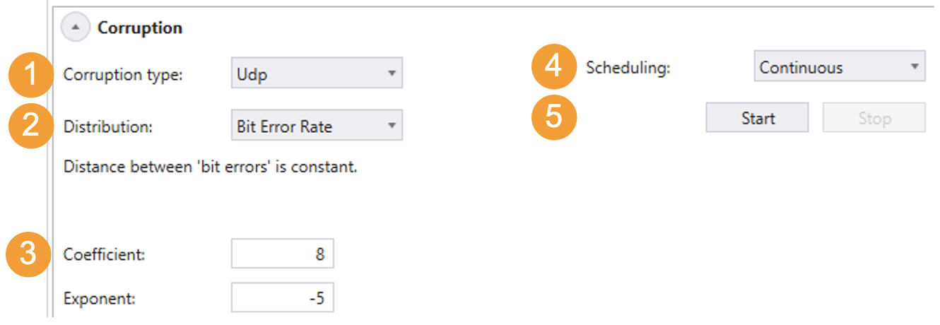
Fig. 6.44 UDP checksum configuration in the UI.
To configure UDP checksum corruption:
Configure the protocol layer to corrupt (e.g. UDP).
Select the relevant distribution from the distribution dropdown menu (e.g. Bit Error Rate).
Supply the parameters to configure the selected distribution (e.g. Coefficient = 8, Exponent = -5)
Select the relevant scheduler function from the dropdown menu (e.g. Continuous).
Press Start to activate the impairment.
The configuration above will cause an UDP checksum error to be inserted into the packet flow for every 8 * 10-5 bits of packet data.
Note
The example below illustrates how to configure corruption as illustrated Fig. 6.44.
PE_CORRUPT  [fid ]   UDP (3)
PED_SCHEDULE[fid7,4] 1   0
PED_BER     [fid7,4] 8   -5
PED_ENABLE  [fid,0]  ON
Flow BW Control
Chimera implements policers at every flow input, which will drop all packets that exceed the configured bandwidth (CIR) and burst size (CBS).
Likewise, Chimera implements shapers at the output, which will shape the outgoing traffic to a configurable bandwidth (CIR) and burst size (CBS). If excess packets are available, there is a buffer of configurable size (Buffer size) for storing excess packets. If the buffer overflows due to shaper BW limiting, packets will be dropped.
Policers and shapers implement a leaky bucket and update the current fill level. The fill level is reduced with the rate specified by CIR and increased with the packet size when a packet is forwarded. If the bucket fill level is above the CBS when a packet arrives at the policer / shaper, the packet will be dropped (policer) or held back (shaper). If the fill level is below the CBS, the packet will be forwarded, and the size of the packet is added to the fill level.
It is configurable whether the policer and shaper will be applied at layer 1 or layer 2. When configured for layer 2, only the Ethernet packets starting with the DMAC and ending with the FCS are counted as part of the traffic. When shaping at layer 1 the minimum IPG (= 12 bytes) and the preamble (= 8 bytes) are considered part of the traffic.
When configuring the parameters of the policer and shaper, the following limits apply:
Parameter |
Legal values |
Comments |
Step size |
|---|---|---|---|
CIR |
0 to 1,000,000 |
Value is multiplied by 100 kbps |
1 (= 100 kbps) |
CBS |
0 to 2,097,152 |
Bytes |
1 byte |
Buffer size |
0 to 2,097,152 |
Bytes |
128 bytes |
Furthermore, the CBS must be configured >= maximum packet size in flow + 64 bytes to function correctly.
Important
Policers and shapers do not support any impairment distributions or scheduler functions.
Ingress policers (iid = 5)
Configuration of the ingress policer using the UI is illustrated Fig. 6.45.
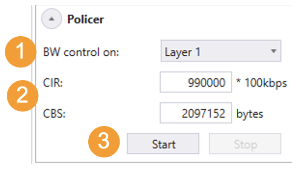
Fig. 6.45 Configuring flow policer in the UI.
To configure ingress policer:
Select at which layer to implement the policer from dropdown menu (e.g. Layer 1).
Supply the parameters to configure policer (e.g. CIR = 9.9 Gbps, CBS = 2 Mbyte)
Press Start to activate the policer.
Note
The example below illustrates how to configure the policer as illustrated Fig. 6.45.
PE_BANDPOLICER [fid] ON L1 990000 2097152
Egress Shapers (iid = 6)
Notice that the shapers are located before the packet duplication in the impairment pipeline. I.e., if packet duplication is configured, duplicate packets are added to the flow after the shaper, and the resulting output bandwidth will be higher than the one configured in the shaper.
Furthermore, the amount of memory allocated for the shaper buffer will be taken from the buffer used for generating latency, so when memory is allocated for shaper buffering, the guaranteed lossless latency listed in Table 3 will decrease accordingly.
Configuration of the shaper using the UI is illustrated Fig. 6.46.
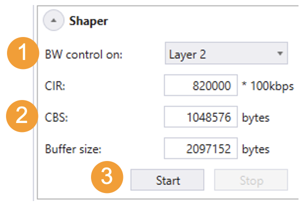
Fig. 6.46 Configuring flow shapers.
To configure egress shaper:
Select at which layer to implement the shaper from dropdown menu (e.g. Layer 2).
Supply the parameters to configure the shaper (e.g. CIR = 8.2 Gbps, CBS = 1 Mbyte, Buffer Size = 2 Mbyte)
Press Start to activate the impairment.
Note
The example below illustrates how to configure the shaper as illustrated Fig. 6.46.
PE_BANDSHAPER [fid] ON L2 820000 1048576 2097152
Latency / Jitter (iid = 2)
The latency / jitter impairment differs significantly from the other impairments described above, because it affects the delay of each packet. As a consequence, the distributions which can be assigned to the latency / jitter impairment define latencies rather than the distance in packets between two impaired packets. Figure 47 illustrates how to configure a flow for a Gaussian jitter distribution with an average delay of 50 us and a standard deviation of 2.5 us.
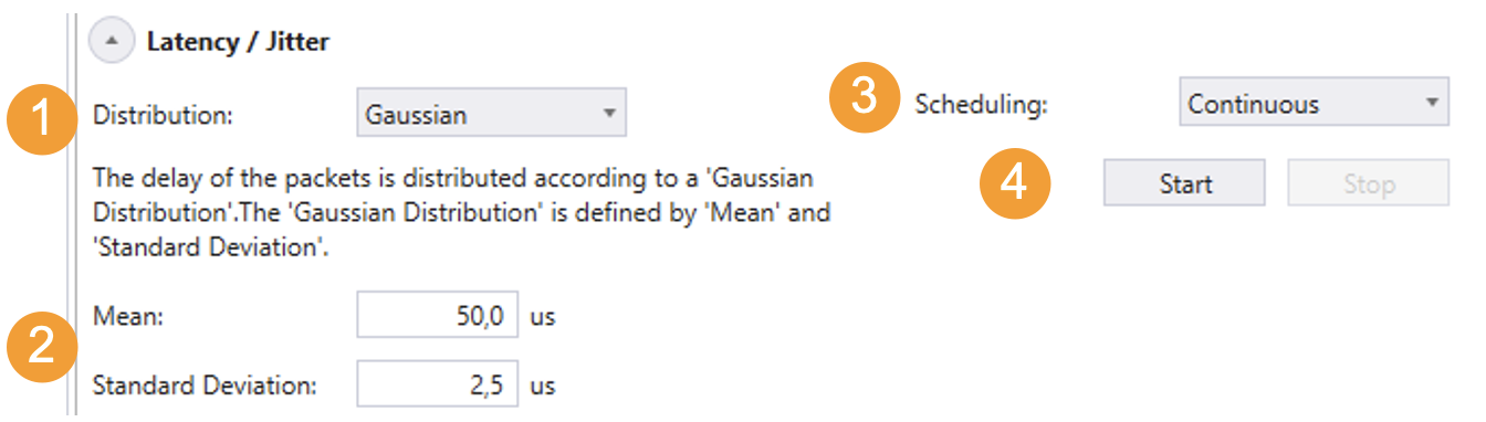
Fig. 6.47 Latency jitter configuration in the UI.
(There is no configuration of the impairment for latency / jitter).
To configure latency / jitter:
Select the relevant distribution from the distribution dropdown menu (e.g. Gaussian).
Supply the parameters to configure the selected distribution (e.g. Mean = 50.0 us, Standard Deviation = 2.5 us.).
Configure the scheduler (e.g. Continuous).
Press Start to activate the impairment.
To stop dropping packets, press stop.
The configuration shown Fig. 6.47 will cause a Gaussian jitter distribution to be applied to the packets on the flow.
Note
The example below illustrates how to configure the same configuration using script commands.
PED_GAUSS [fid,2] 50000 2500
PED_ENABLE[fid,0] ON