Runt
A “runt” Ethernet frame is a term used in networking to describe an Ethernet frame that is too short to be valid according to Ethernet standards. Ethernet frames are supposed to adhere to a minimum length to ensure that the signal propagates properly across the network medium and can be reliably detected by receiving devices. The minimum frame length for Ethernet typically includes the data payload, frame header, and frame check sequence (FCS).
In a standard Ethernet frame, the minimum length is 64 bytes. If an Ethernet frame is shorter than this minimum length, it is considered a “runt” frame. Runt frames can be the result of various issues, such as collisions on the network, transmission errors, or improper frame encapsulation.
Runt frames are typically discarded by Ethernet network interfaces because they are too short to contain valid data. Discarding runt frames helps maintain network integrity and prevents unnecessary processing of invalid or corrupted data.
Port Runt commands allow you to “cut” packets into smaller “pieces”.
As shown in Fig. 3.6, an Ethernet frame typically consists of the following components:
Preamble (7 bytes): The preamble is a sequence of 7 bytes (56 bits) used for synchronization and clock recovery. It helps the receiving Ethernet interface synchronize with the incoming data stream.
Start of Frame Delimiter (SFD) (1 byte): The SFD is a specific bit pattern (10101011) that marks the end of the preamble and the beginning of the frame’s header.
Ethernet Header (Varies in length): The Ethernet header contains various fields, including the source and destination MAC addresses, EtherType (or Length), and sometimes additional information like VLAN tags or Quality of Service (QoS) information.
Data Payload (Varies in length): The data payload contains the actual data being transmitted in the Ethernet frame. Its length can vary depending on the type of Ethernet frame (e.g., Ethernet II, IEEE 802.3).
Frame Check Sequence (FCS) (4 bytes): The FCS is a checksum value calculated over the entire frame (header and data) to detect transmission errors. It helps ensure the integrity of the received frame.
Inter-Frame Gap (IFG) (12 bytes): The IFG is a gap or idle period between Ethernet frames, which ensures that there is enough time for network devices to process the incoming frame and prepare for the next one. It also helps prevent collisions in half-duplex Ethernet networks.
End of Frame (EOF): The EOF marks the end of the Ethernet frame and is used to signal the completion of the frame.
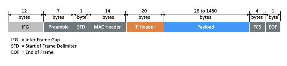
Fig. 3.6 Ethernet frame
The total length of an Ethernet frame can vary depending on factors like the Ethernet standard (e.g., Ethernet II, IEEE 802.3), whether it includes VLAN tags, and the size of the data payload. The minimum frame length for Ethernet is typically 64 bytes (as shown in Fig. 3.7), including all the components mentioned above, but longer frames are also allowed, with a maximum frame size specified by the Ethernet standard (e.g., 1518 bytes for standard Ethernet). Frames shorter than the minimum are considered “runt” frames and are often discarded as they may not provide sufficient time for network devices to operate correctly.
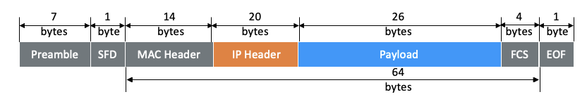
Fig. 3.7 64-byte Ethernet frame
On the TX side, to “cut” an Ethernet frame into a runt frame, use P_TXRUNTLENGTH. The runt frame length starts from the MAC header as shown in Fig. 3.8. An EOF byte will be placed after the runt frame, and the rest becomes idle bytes as shown in Fig. 3.9. To remove the Preamble, use P_TXPREAMBLE_REMOVE with off, illustrated in Fig. 3.10.
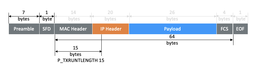
Fig. 3.8 Runt frame of 15 bytes on TX side
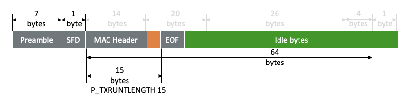
Fig. 3.9 An EOF byte will be placed after the runt frame, and the rest becomes idle bytes
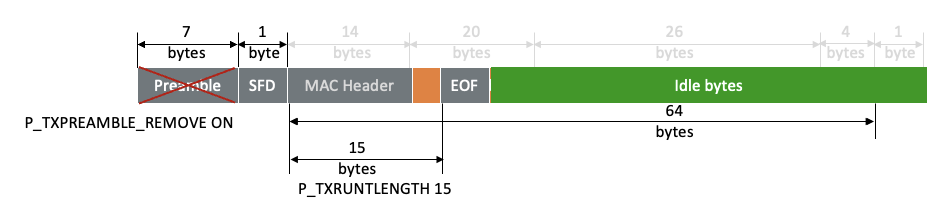
Fig. 3.10 Remove preamble on TX side
What is on the line will be a runt frame of the length you configured as illustrated in Fig. 3.11.
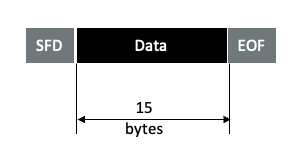
Fig. 3.11 What is on the line
On the RX side, as shown in Fig. 3.12, use P_RXRUNTLENGTH with the same value on the TX side so the port extends the packet size to 64 bytes by converting the “old” EOF byte to a data byte with value FD and also converting the following idle bytes to data bytes with value 07. If other bytes than idle bytes are seen, they will be included in the 64-byte packet.
Use P_TXPREAMBLE_REMOVE with on to recover the preamble, which is required for upper layers to “see” the packet, as shown in Fig. 3.13.
Note
There is no valid FCS in the rebuild packet
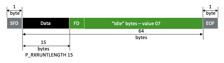
Fig. 3.12 Runt frame of 15 bytes on RX side
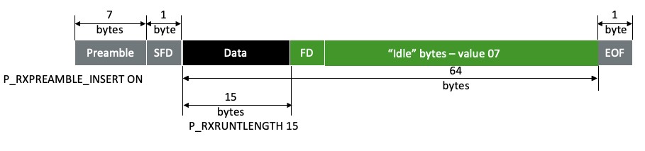
Fig. 3.13 Recover preamble on RX side
The capture in Fig. 3.14 shows what is on the RX side.
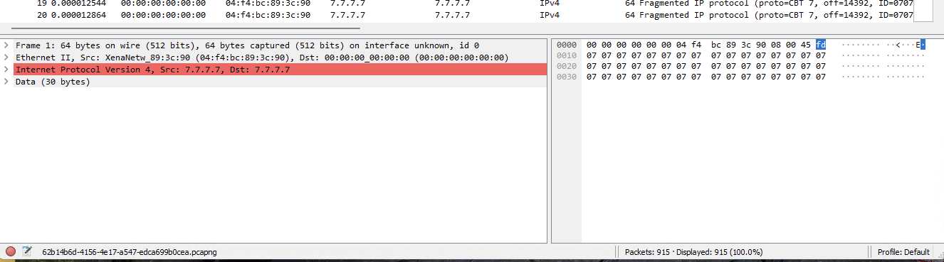
Fig. 3.14 Capture on RX side
Important
Traffic rate must not exceed 10,500,000 packets per second at 10G line rate.
At the receiver there must be minimum 80 bytes from start of one packet until start of next packet.
Packet sizes supported: 15-63 bytes.
Test module supported: Odin-10G-1S-6P[b]